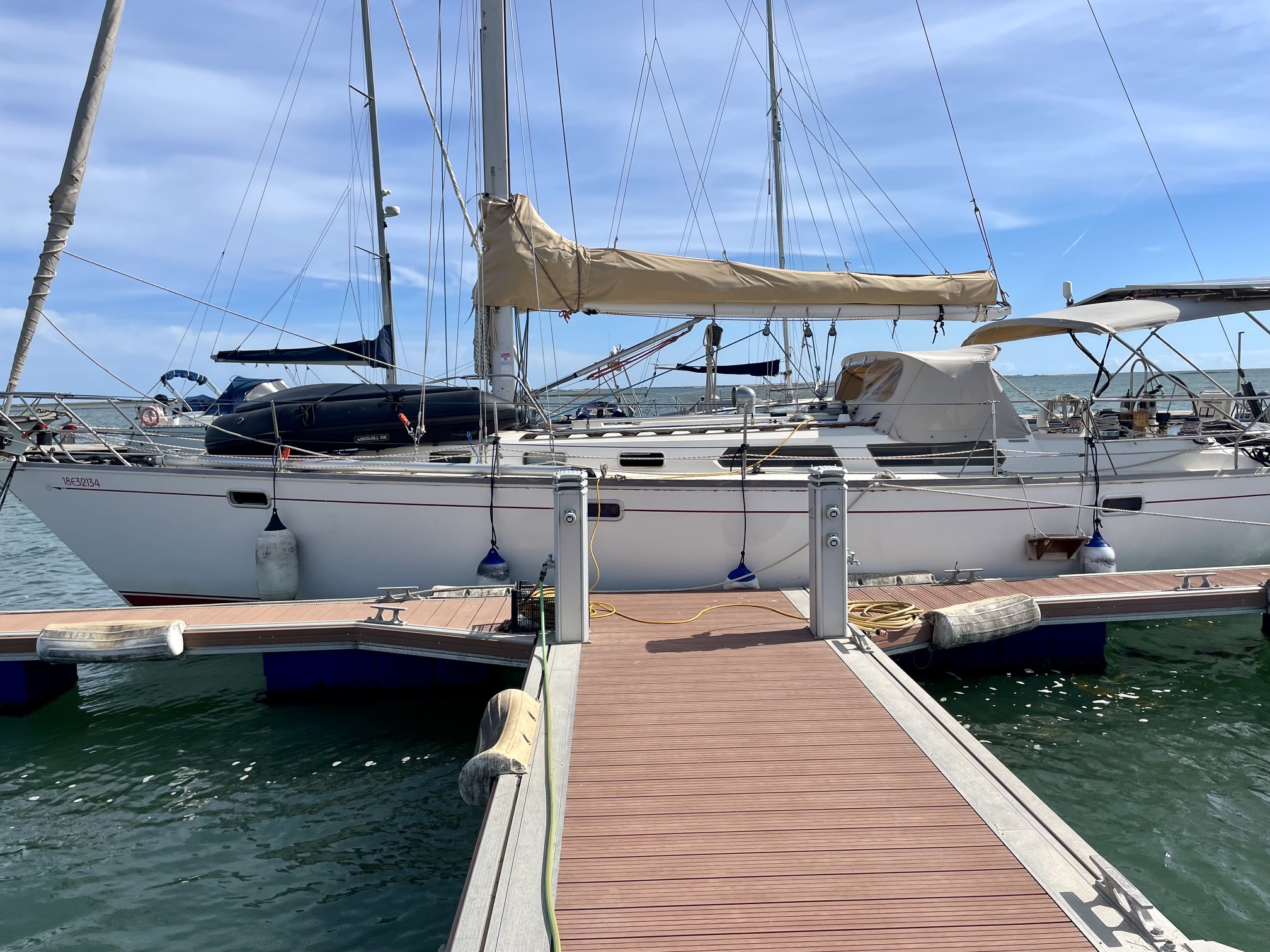
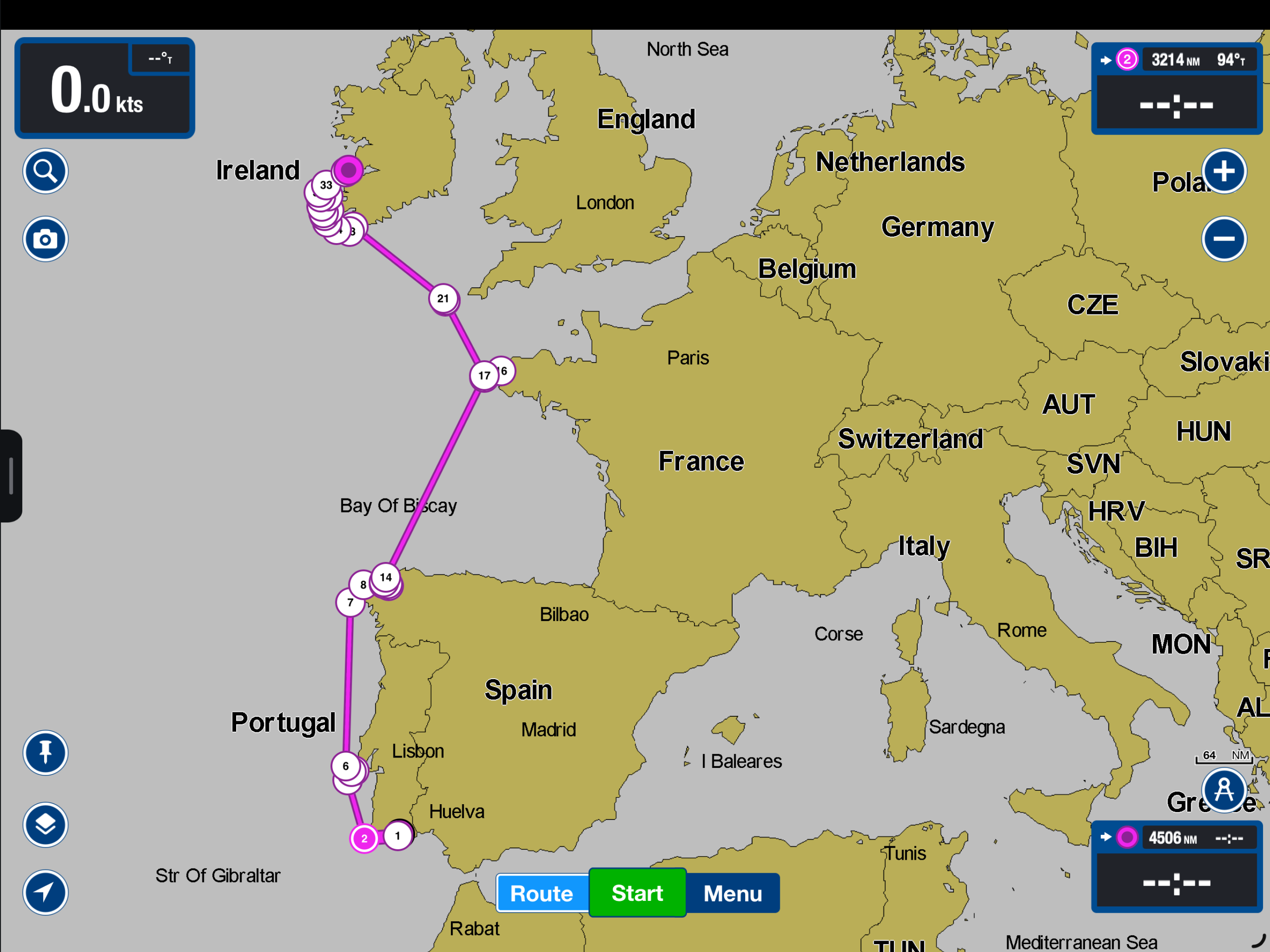
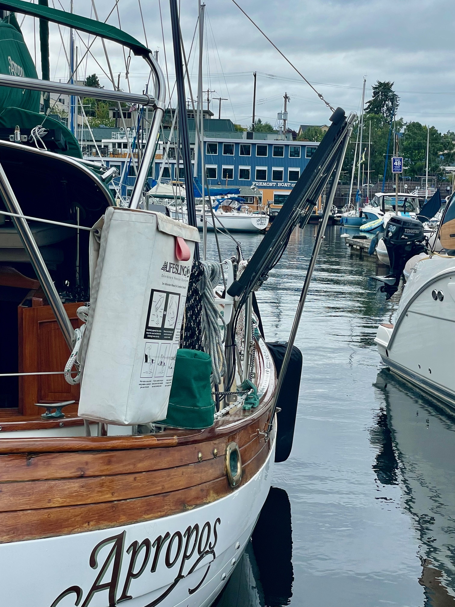
I had an opportunity to crew on a boat sailing from Portugal to Ireland. The boat was a Sabre 42, a racer/cruiser that the owner had sailed around the Mediterranean Sea for a few years before deciding to move it to the west coast of Ireland. The crew consisted of the owner, a friend from Seattle, and myself. The plan was to coastal cruise from Faro, Portugal, up the Iberian peninsula to Spain, then cross the Bay of Biscay to France, and finally sail to Ireland with a short stop in England. A departure date of May 1 was set in order to avoid the stronger northerlies that typically set up during the summer months. We allowed a full month for this approximately 1200nm passage to account for land days where we would wait out weather. The images below show the boat and our route.
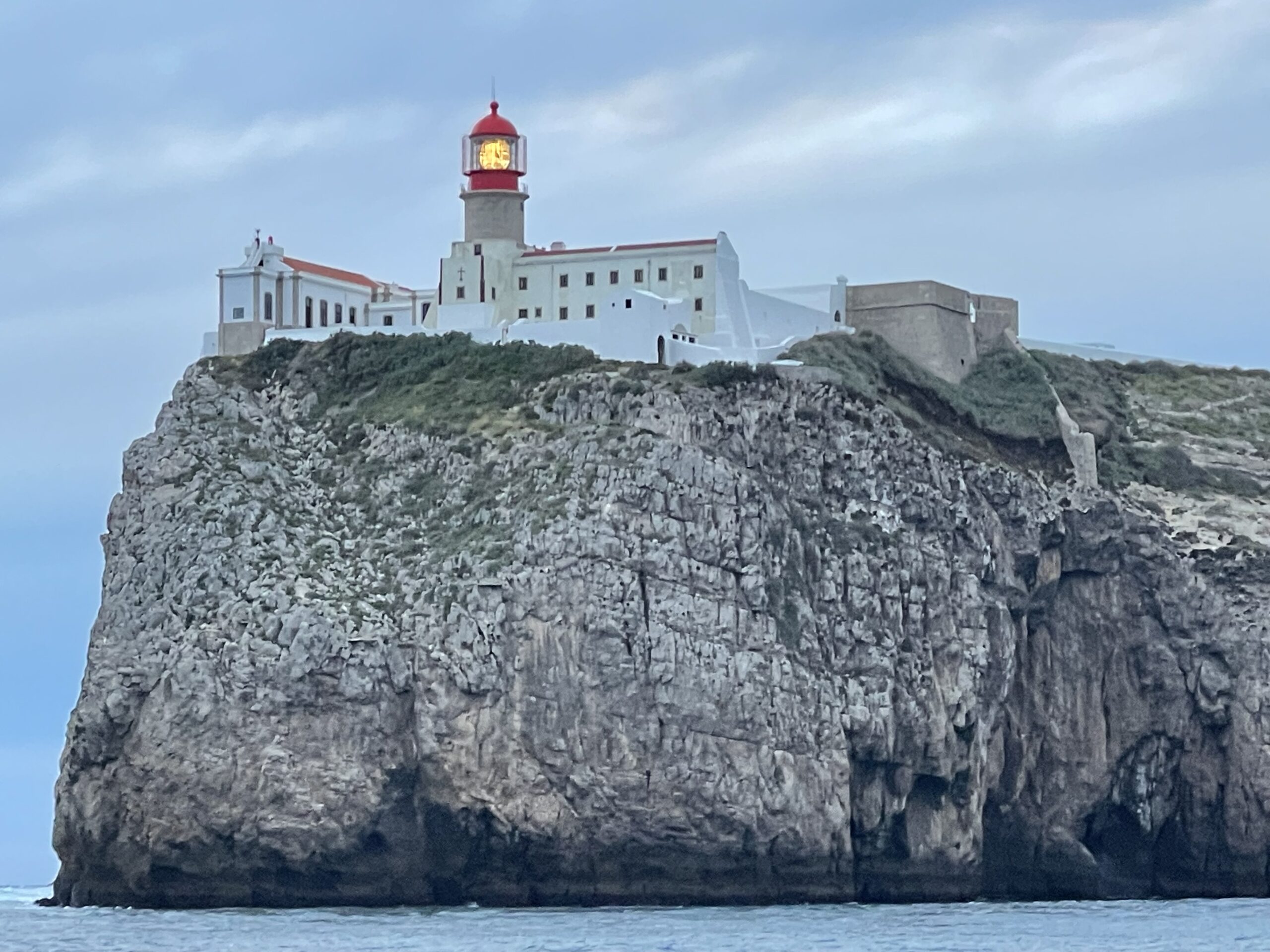
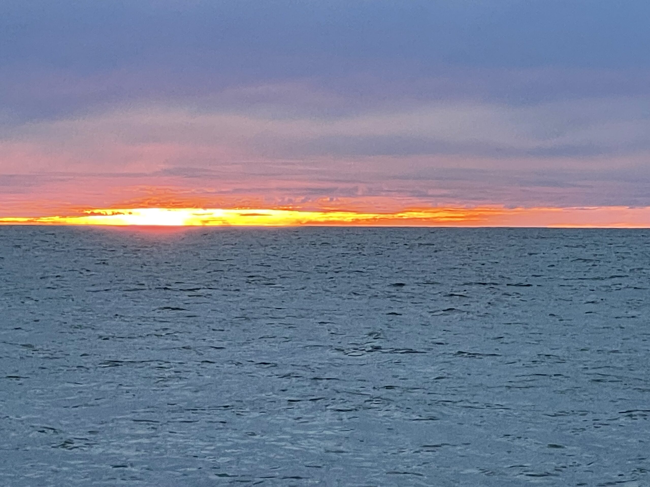
Sabre 42Cabo de Sao Vicente, PortugalSunset at Sea
Portugal
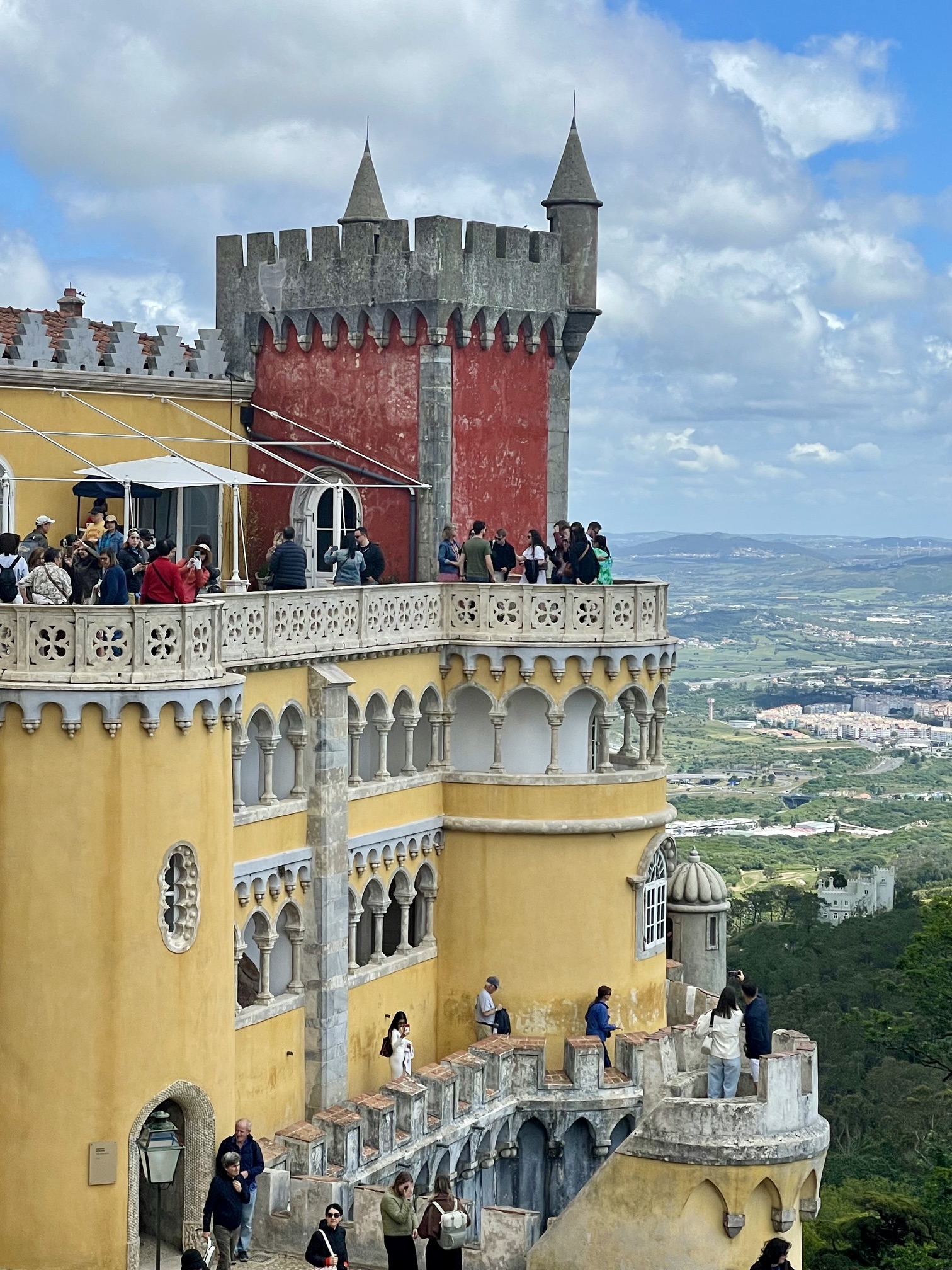
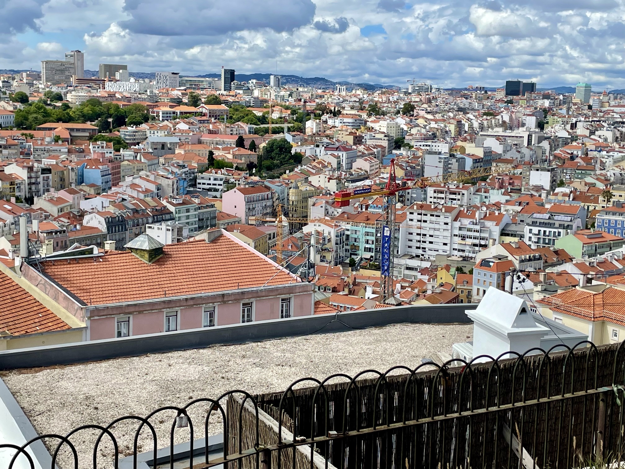
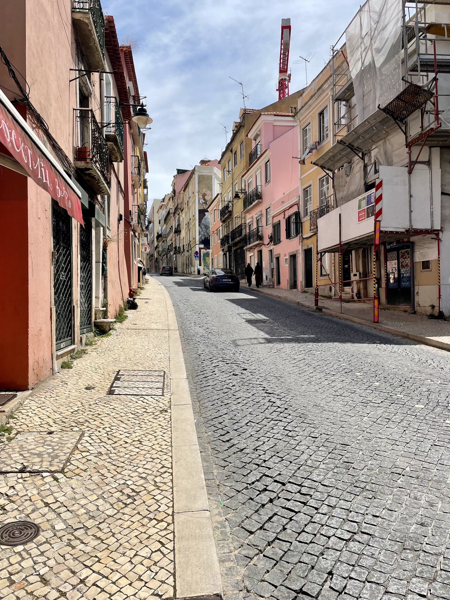
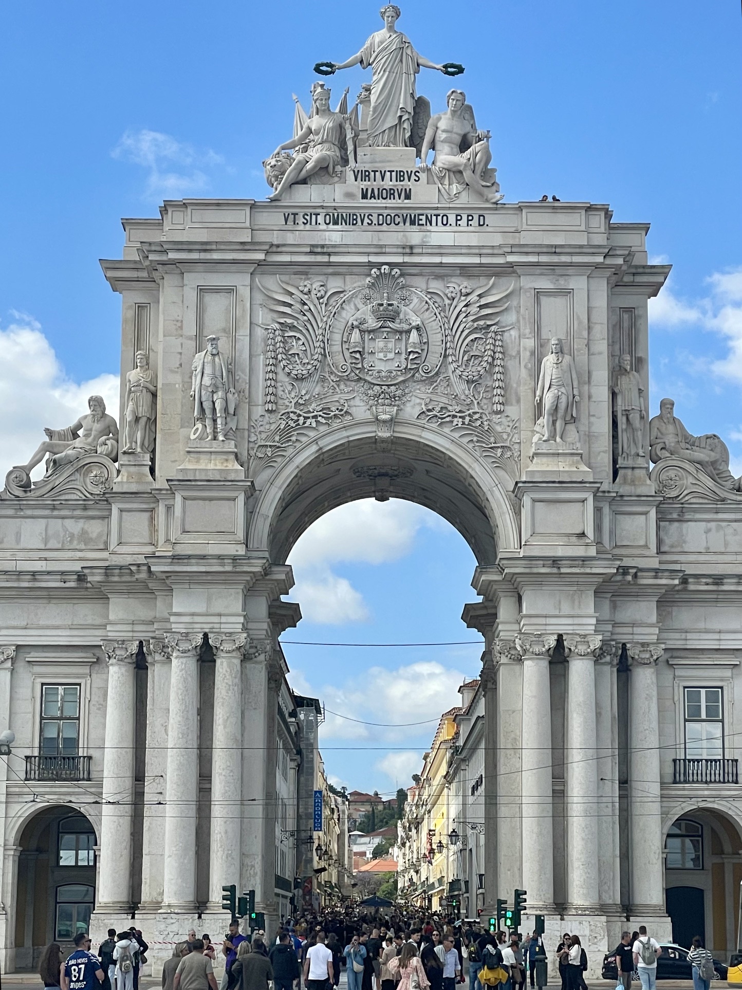
Departed May 1 on a 2-day passage from Faro to Lisbon. Light headwinds had us motor-sailing most of the way. We stayed at Marina De Oeiras which was a few miles from central Lisbon and spent several days touring Lisbon and nearby Sintra.
National Palace in SintraLisbonLisbonLisbon
Spain
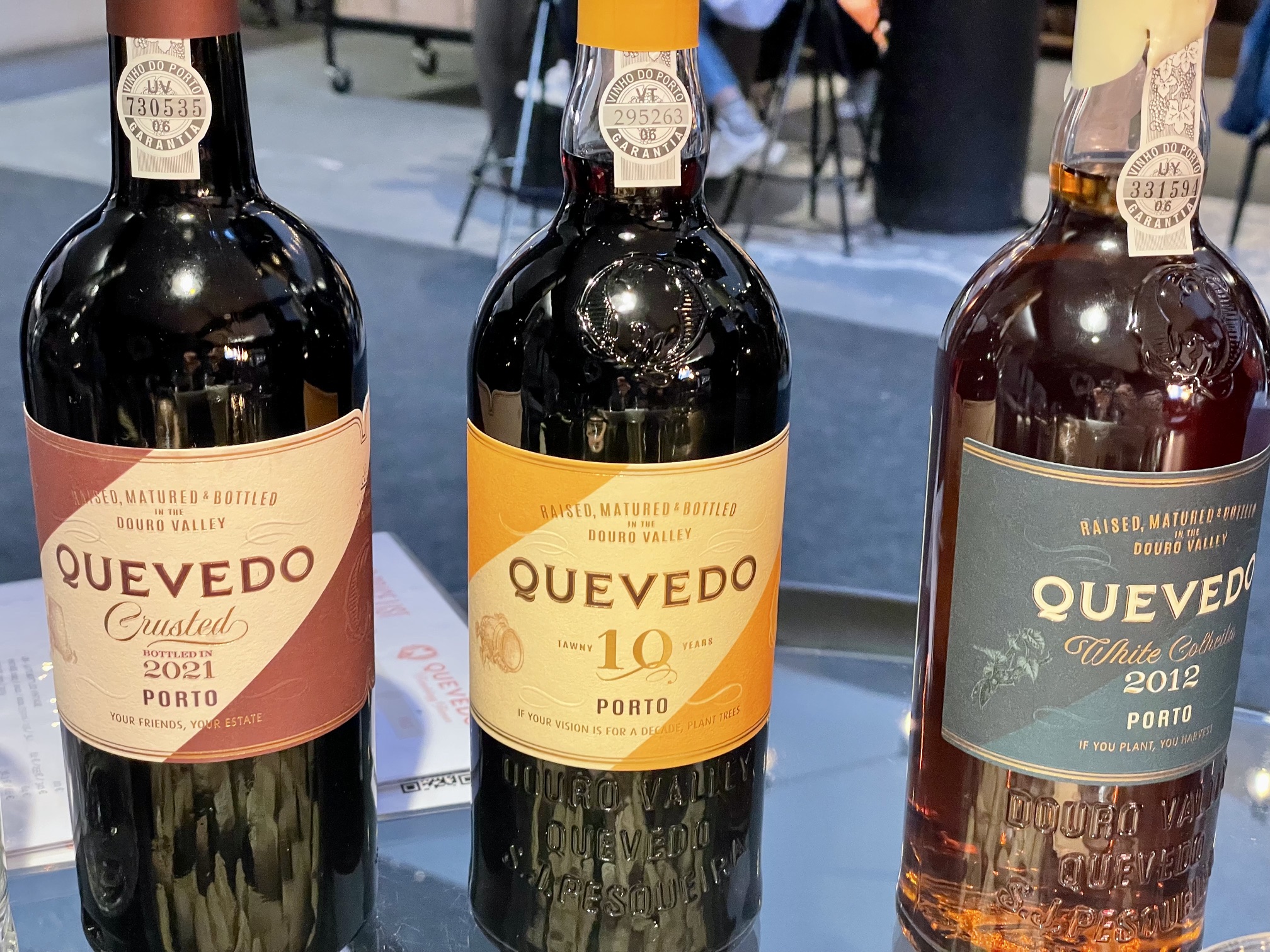
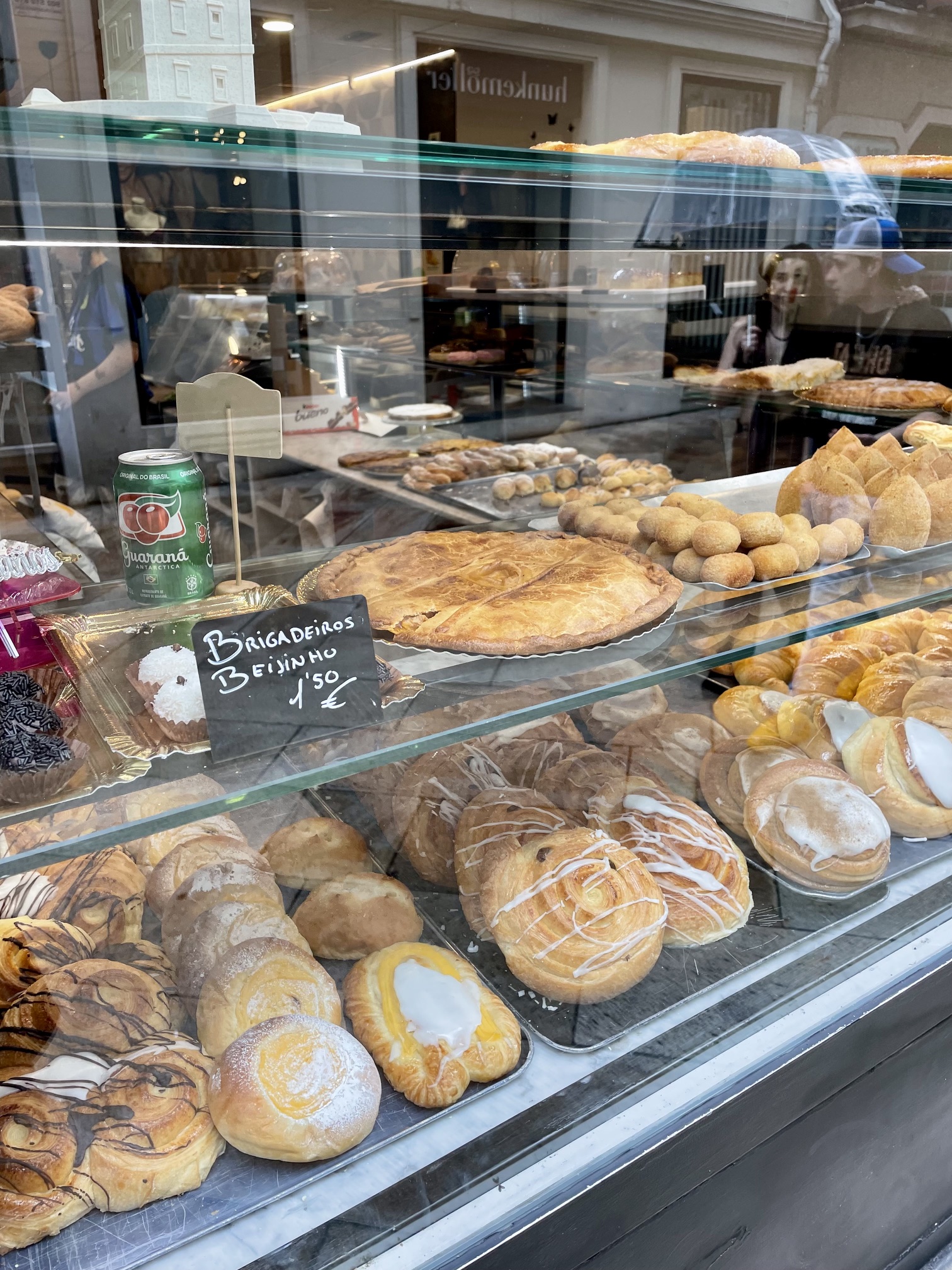
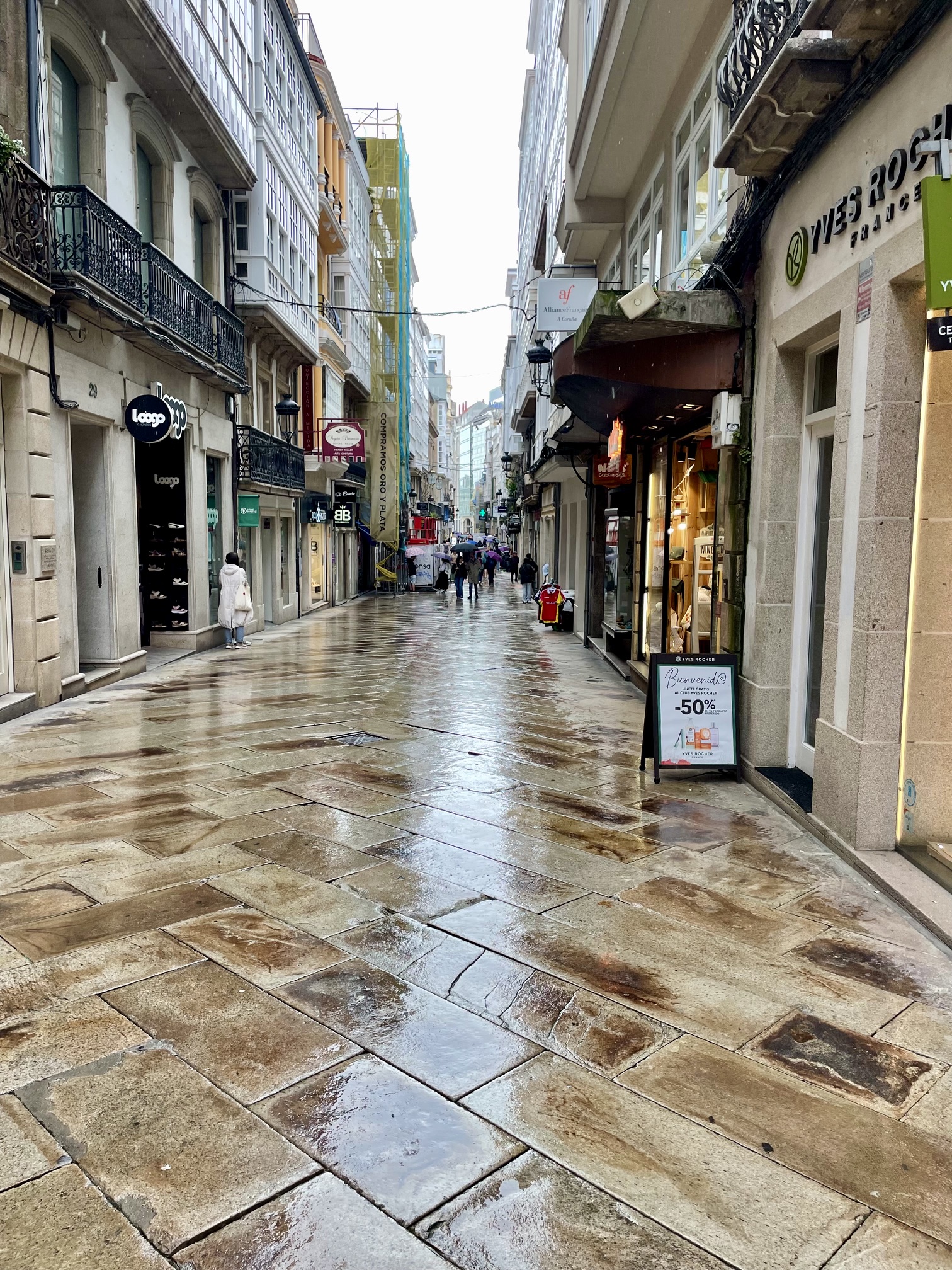
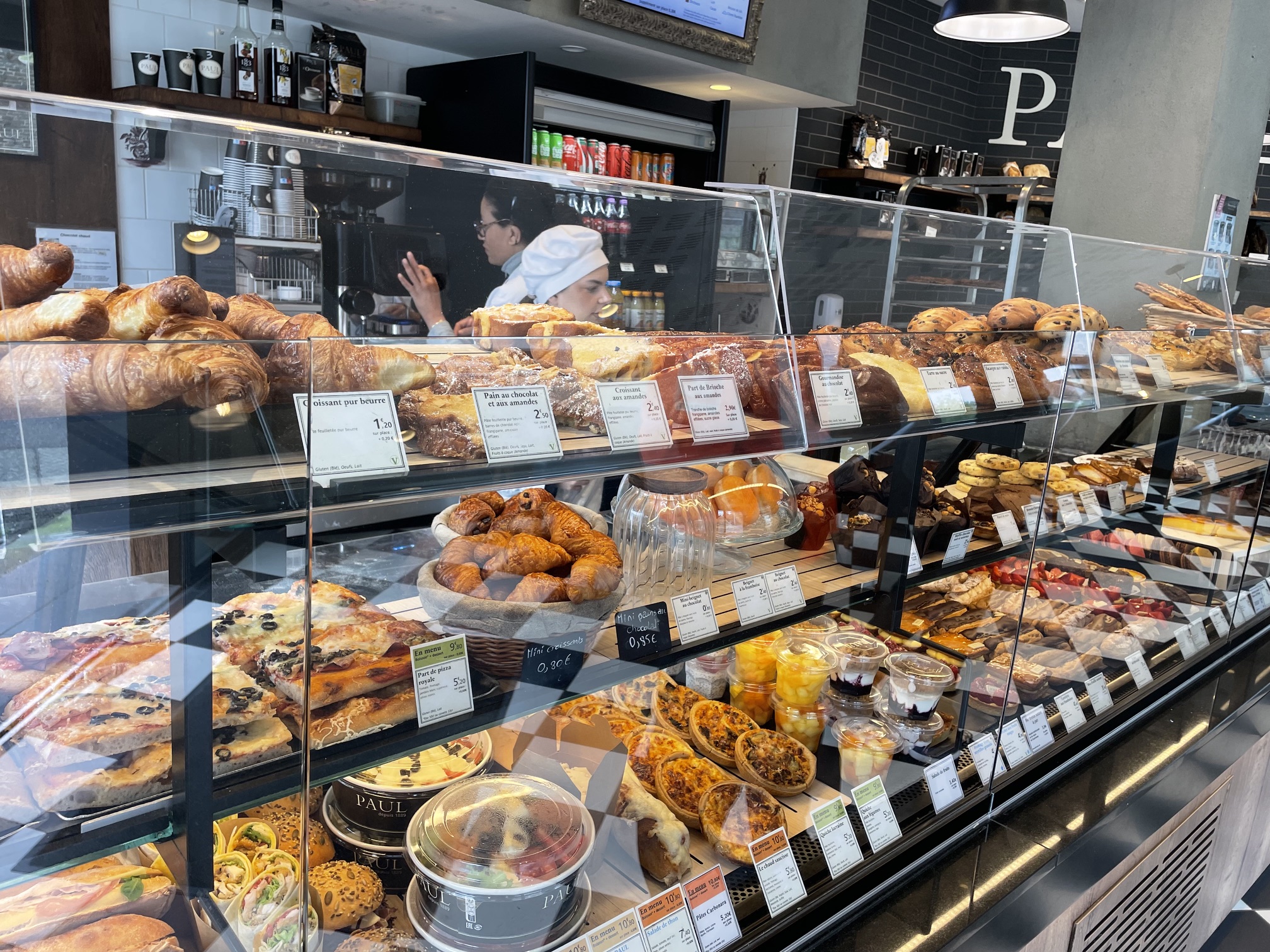
After 3 days in Lisbon waiting for the northerlies to die down, we departed for A ‘Coruna, Spain. A planned stop in Porto was aborted since we had favorable winds that allowed us to sail some, but mostly motor-sail on this 3 day passage. A ‘Coruna was a lovely small town with great bakeries, restaurants, and site-seeing. It got very busy whenever a cruise ship entered the harbor, and returned to quiet when they departed. During our 5-day stay, we rented a car and drove to Porto, Portugal for a day to do some wine-tasting and see the sites.
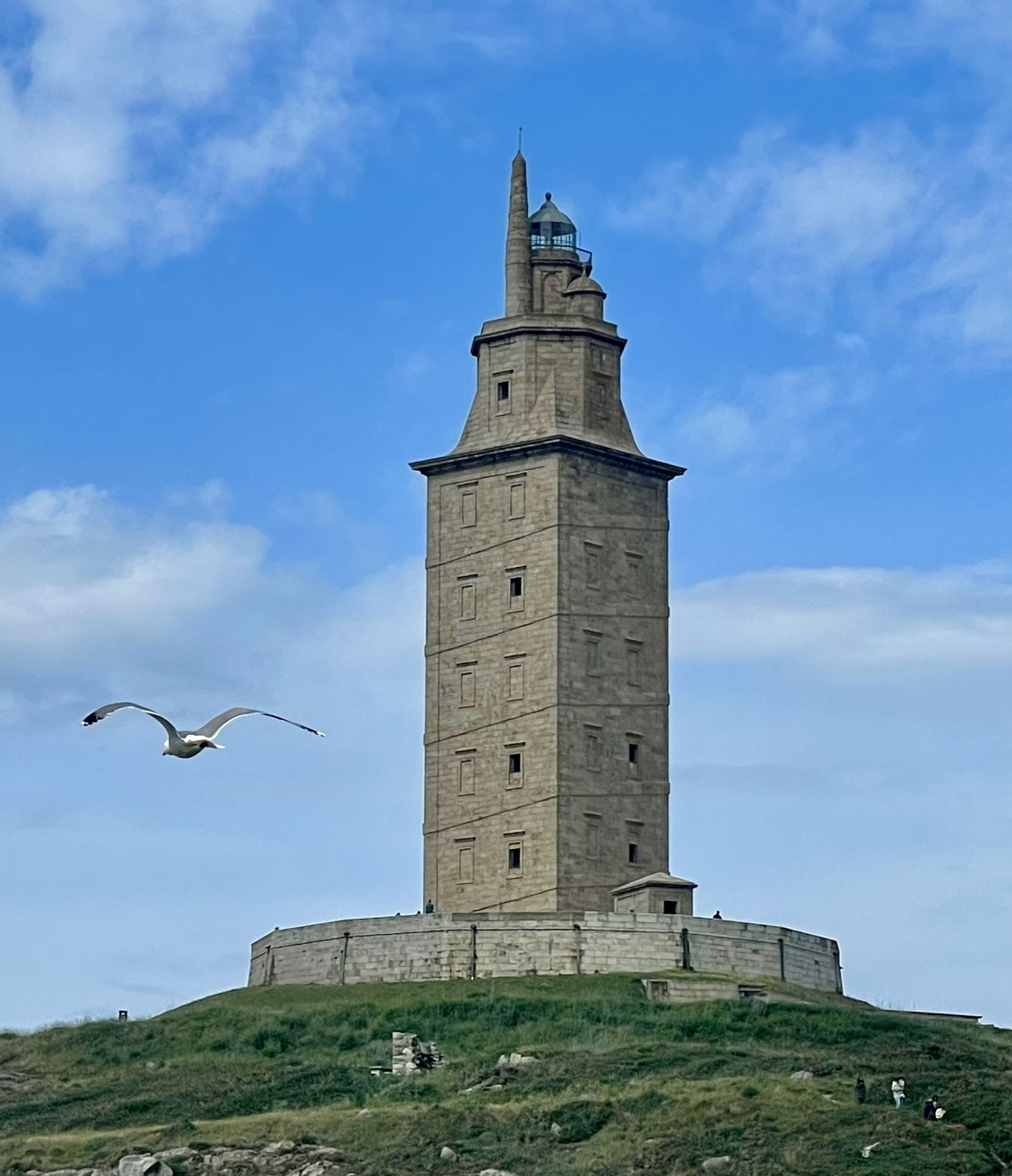
Port Wine TastingBakeryDowntown A ‘Coruna Torre de Hercules
France
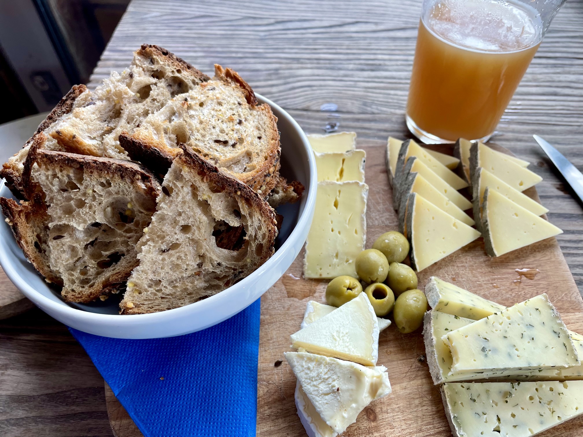
Crossing the Bay of Biscay would be our longest passage. We encountered the strongest winds we would see on the entire trip, and some rainy conditions on day 3. Engine trouble (a broken belt caused the engine to overheat which led to a high-pressure hose failure) caused us to sail the final 50 miles to the river entrance then get towed up-river to the marina in Brest. Brest was another lovely town with great bakeries and restaurants and site-seeing. We were also able to find a hose to fix the engine problem.
One of the few streets in Brest that survived WW2 bombing
England
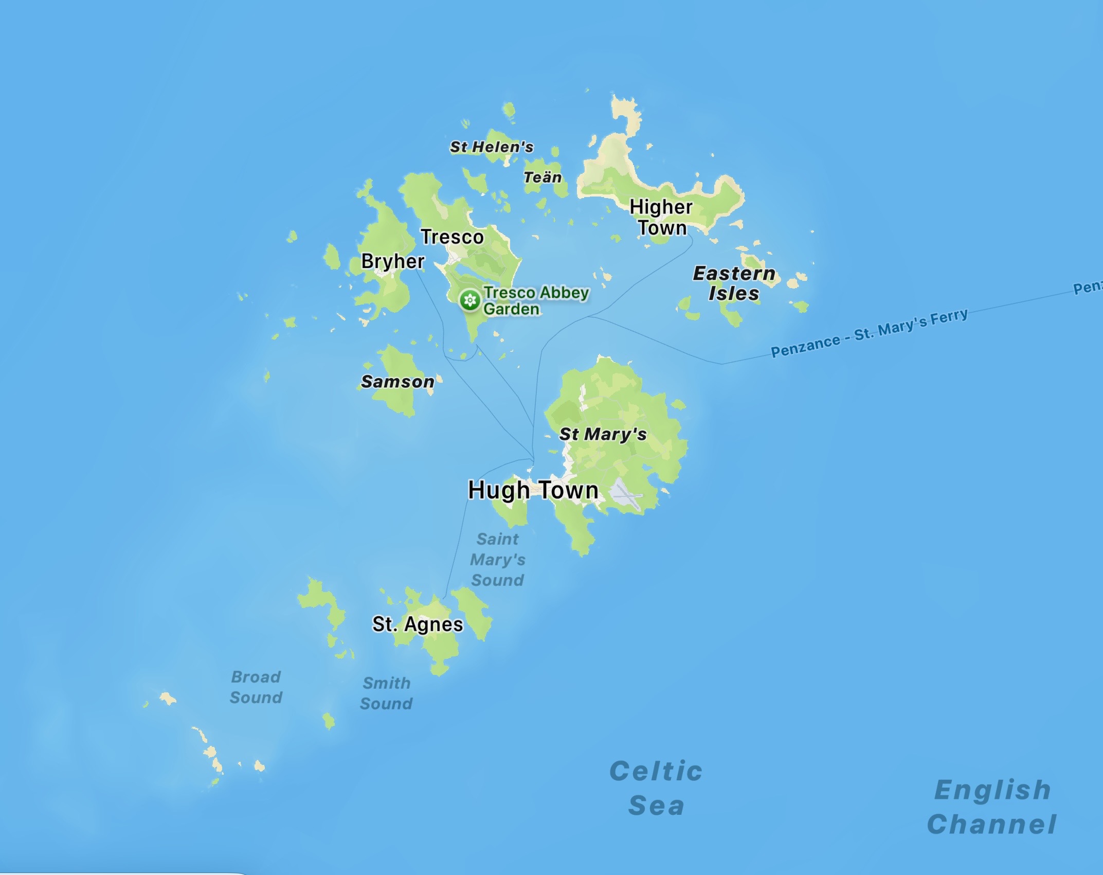
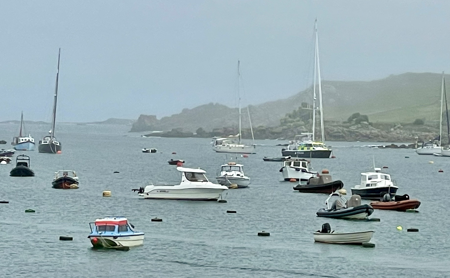
After 4 days in Brest, we departed for a group of islands off the Southern coast of England. This 2-day passage had the best sailing of the trip so far. The boat moved nicely with just 10 knots of wind. We anchored in a bay on St Mary’s in the Isles of Scilly. What we thought would be a quiet anchorage for the 3rd week in May turned out to be quite busy as a weekend festival was going on.
Isles of ScillySt Mary’s Harbour
Ireland
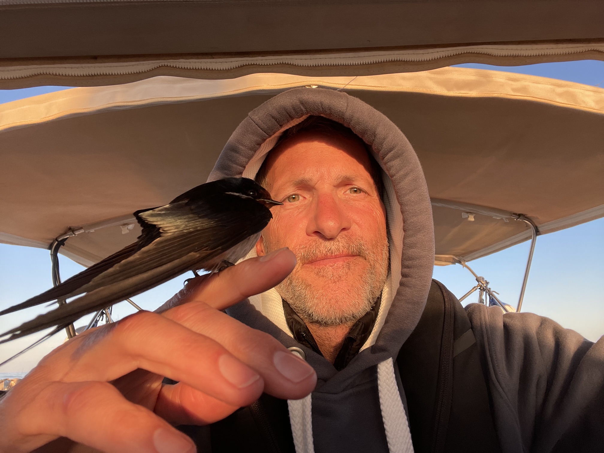
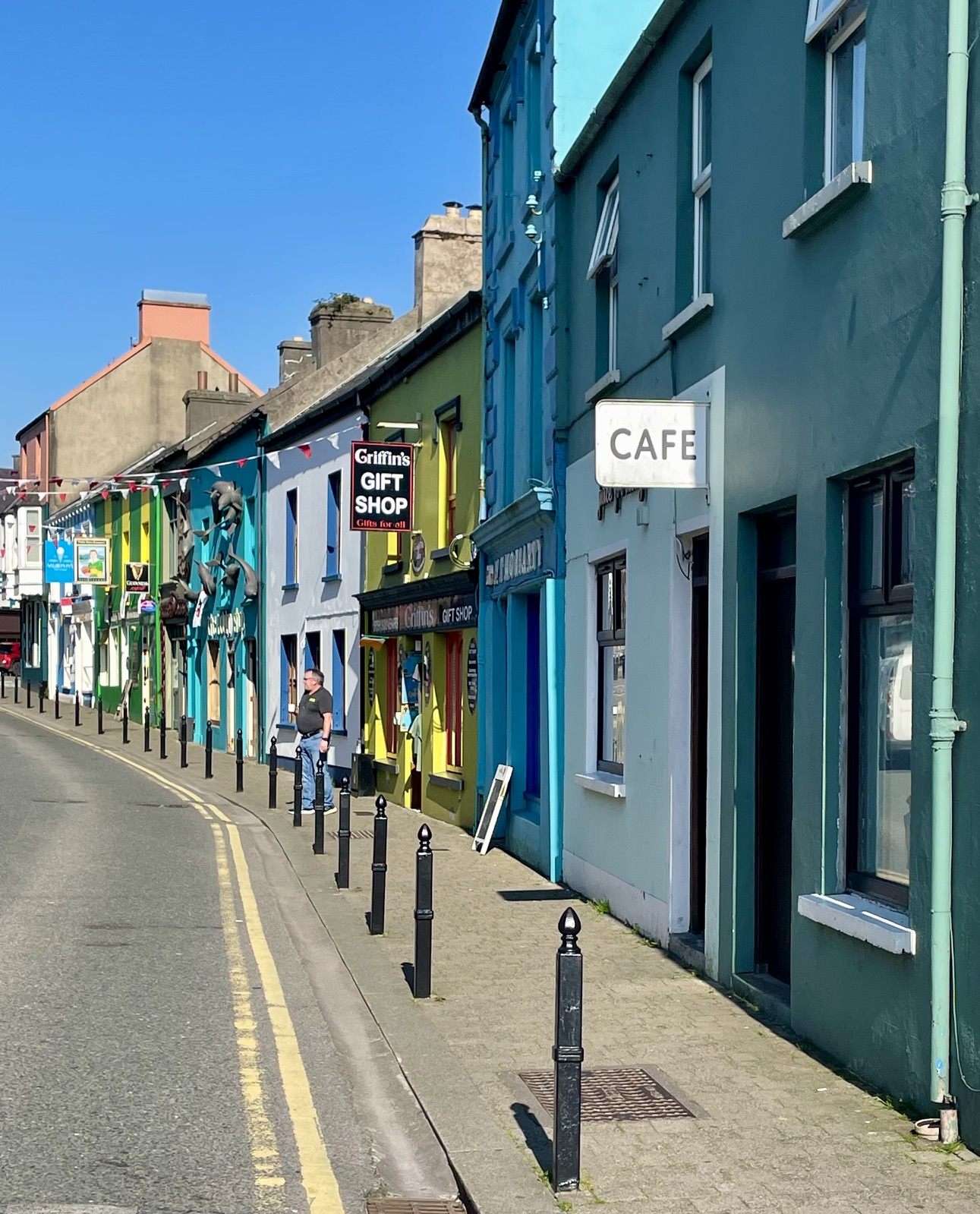
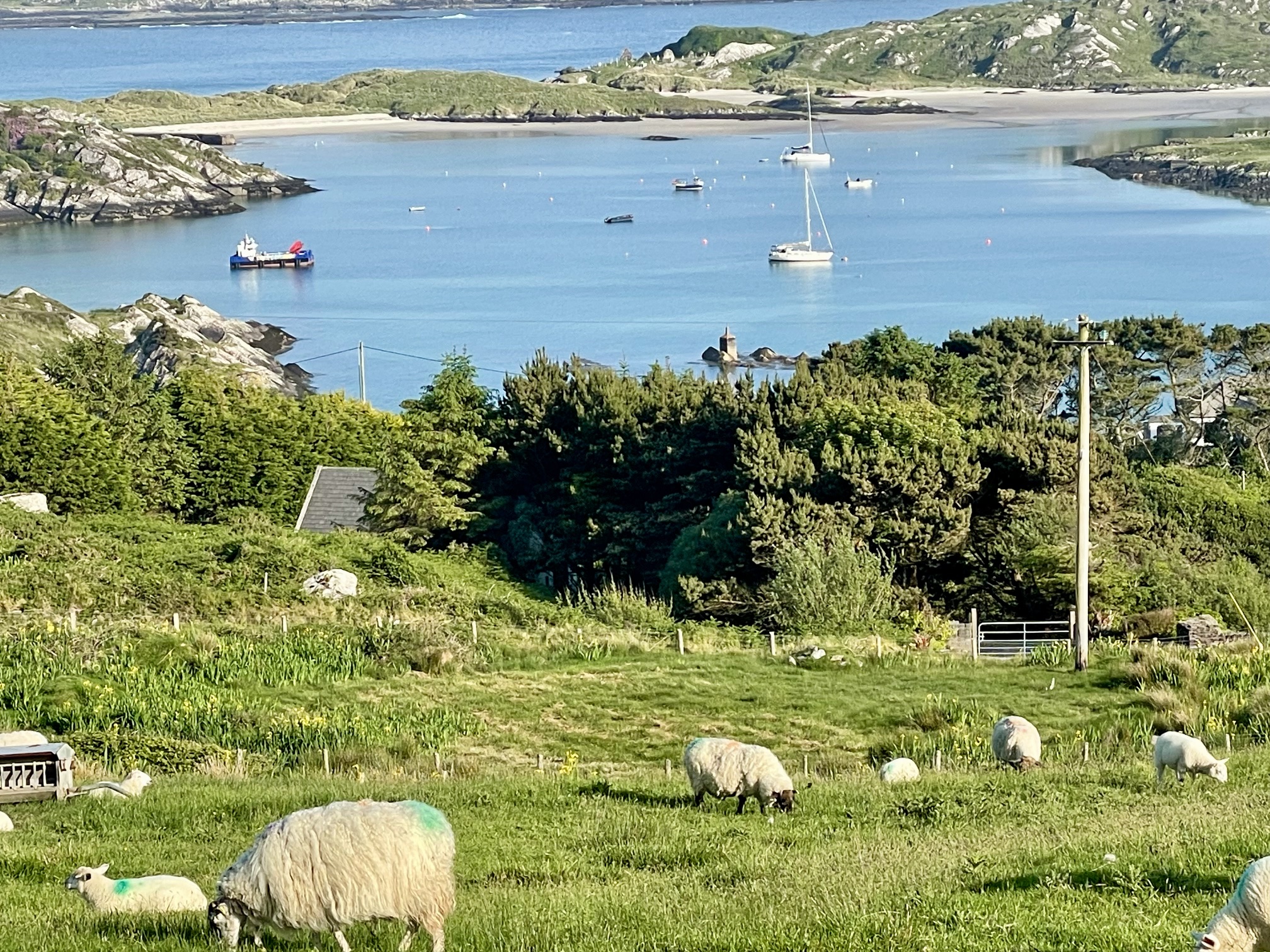
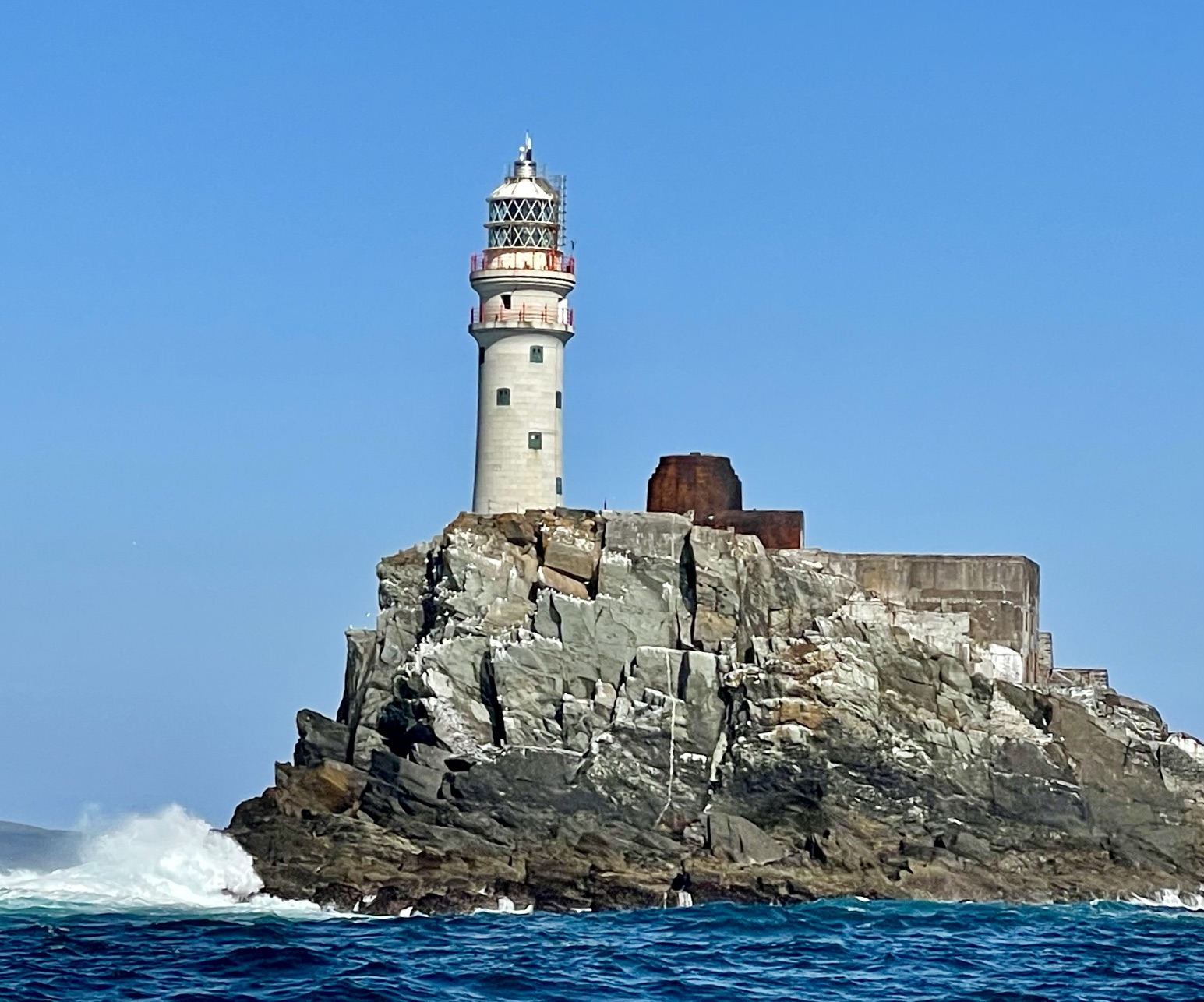
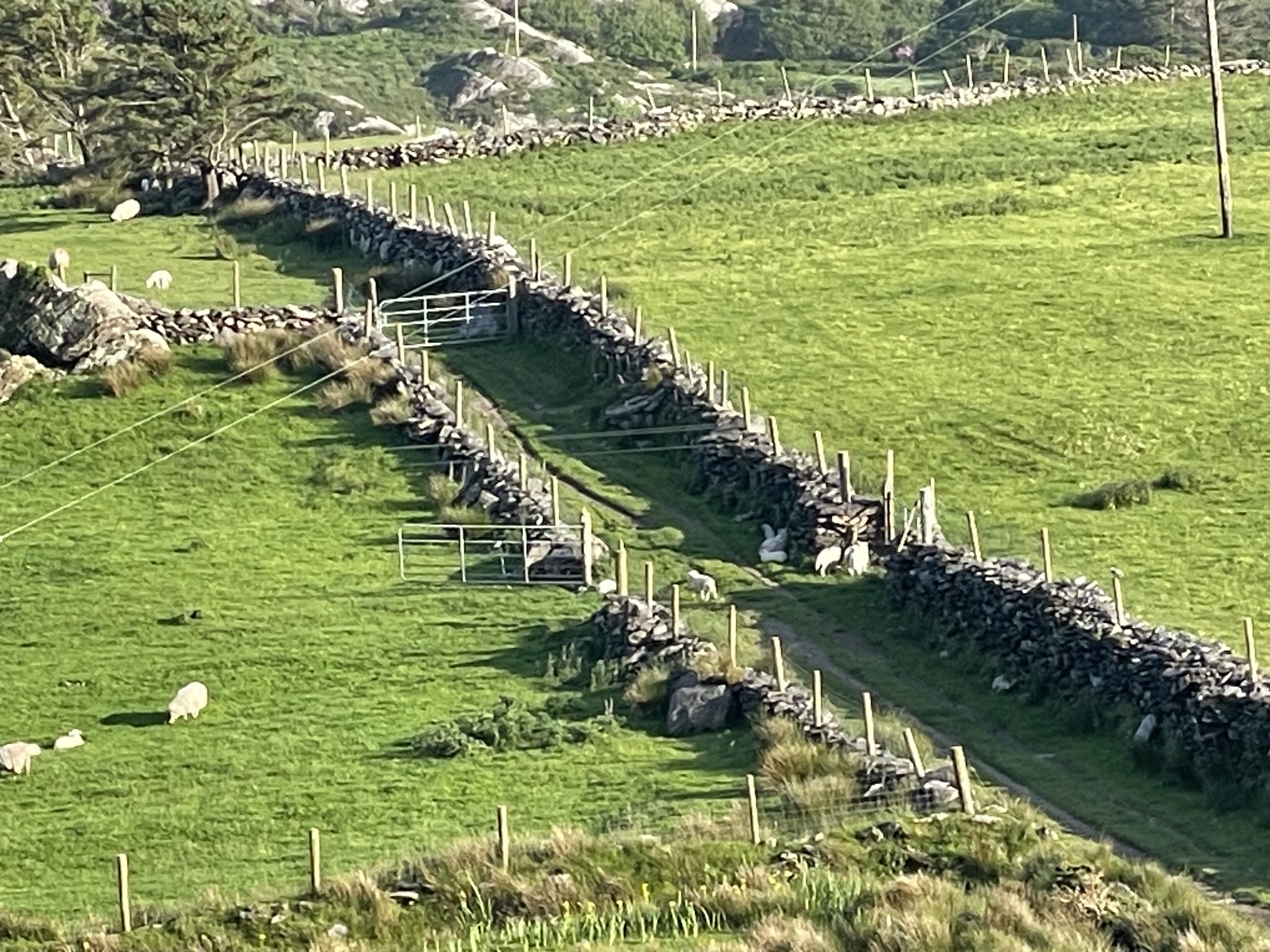
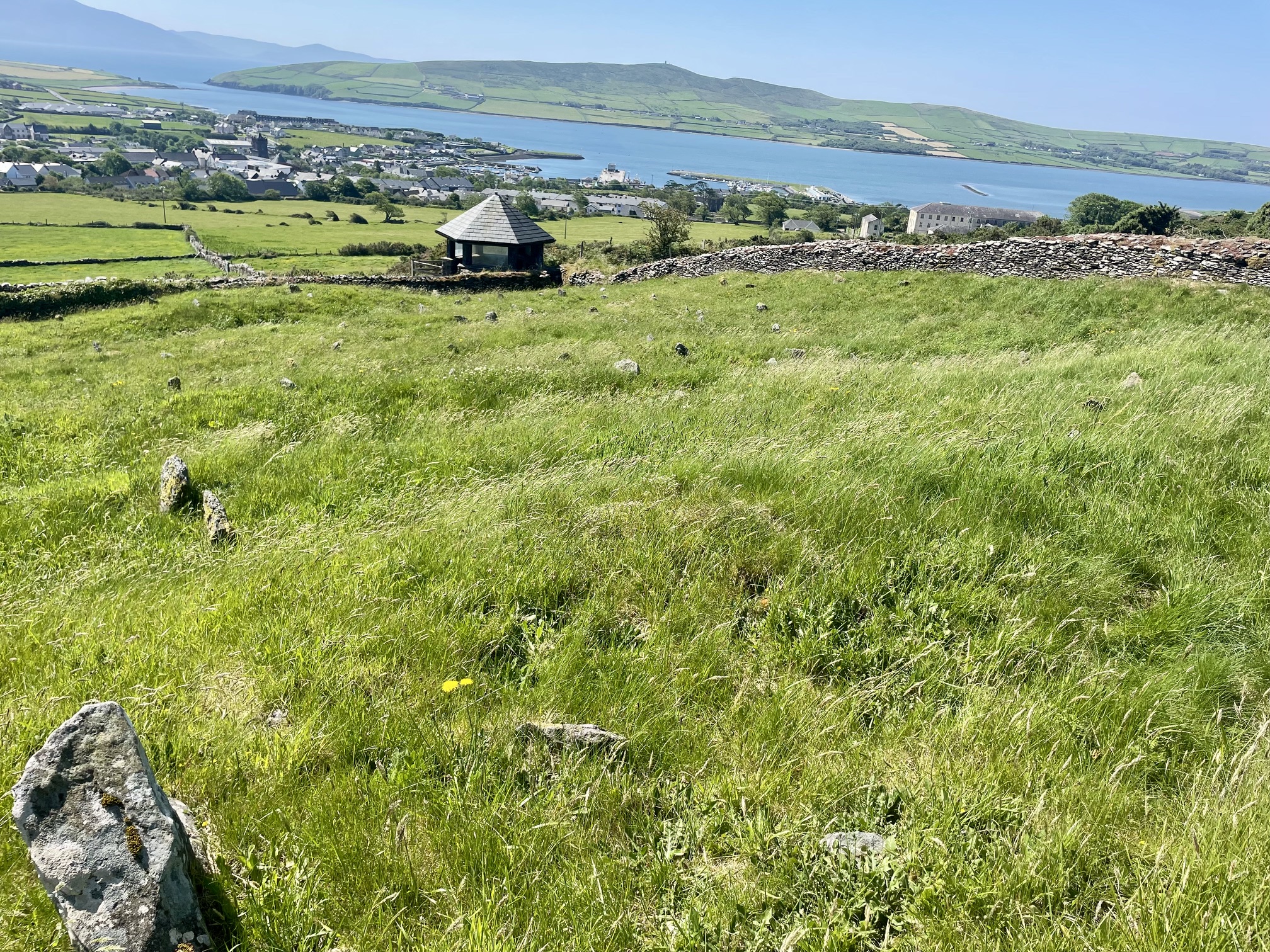
A 2-day passage crossing the Irish Sea was mostly uneventful, except for a visit from a winged friend. We made landfall in Baltimore, a small town along the south end of Ireland. From there we had three, single-day passages along the south-west side of Ireland, stopping at harbors in Derrynane, Dingle, and our final passage to Kilrush on May 30. We had some fantastic sailing on some of these day trips, and the weather was unusually warm and sunny for Ireland!
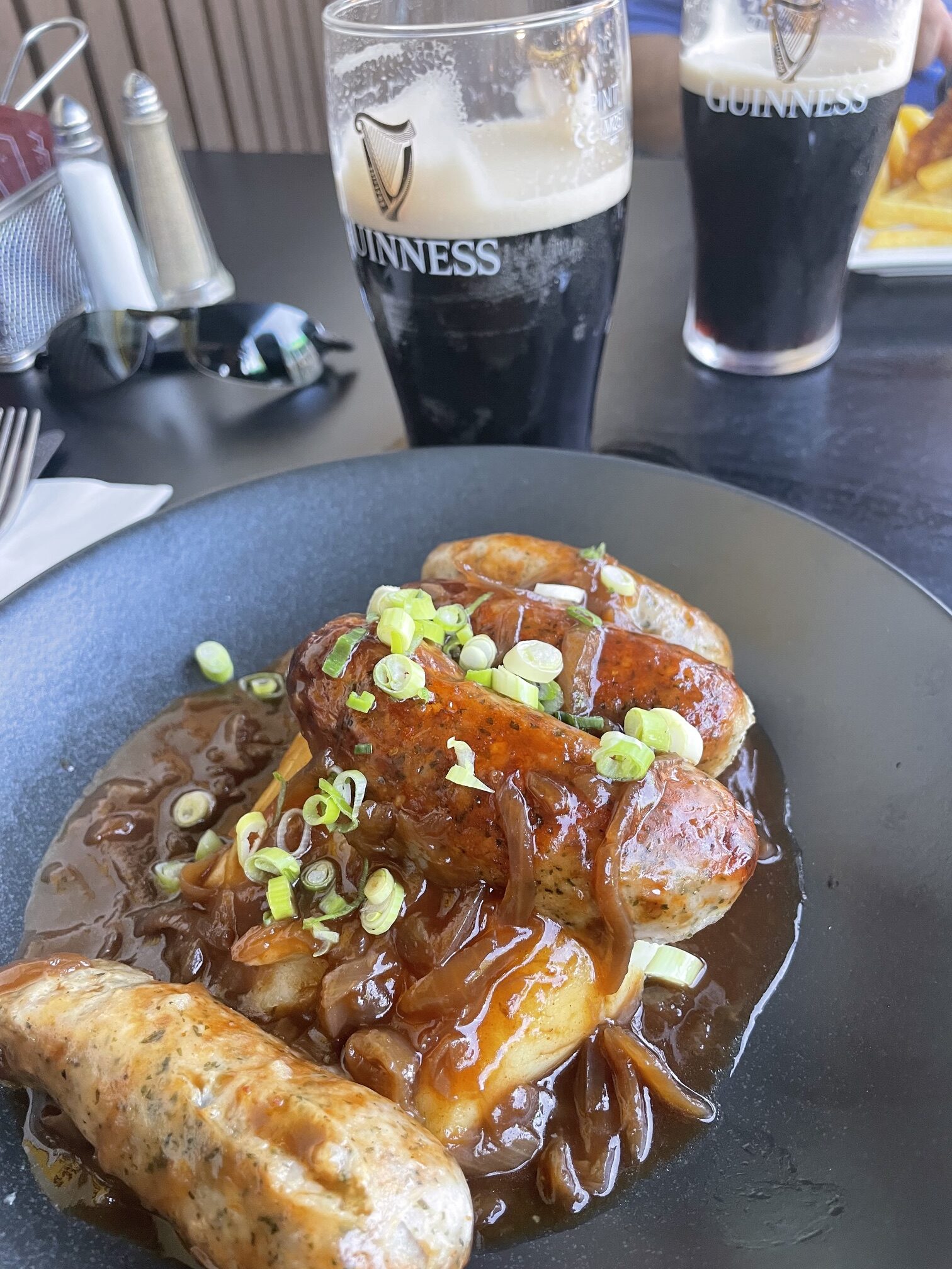
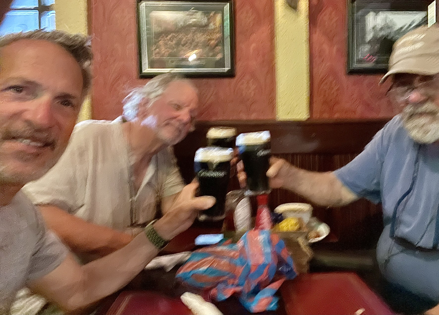
Barn SwallowDingleDerrynane HarbourFastnet Rock/LighthouseStone Fences were everywhereDingle Potato Famine CemeteryBangers & MashGuiness Beer Toast
Dublin
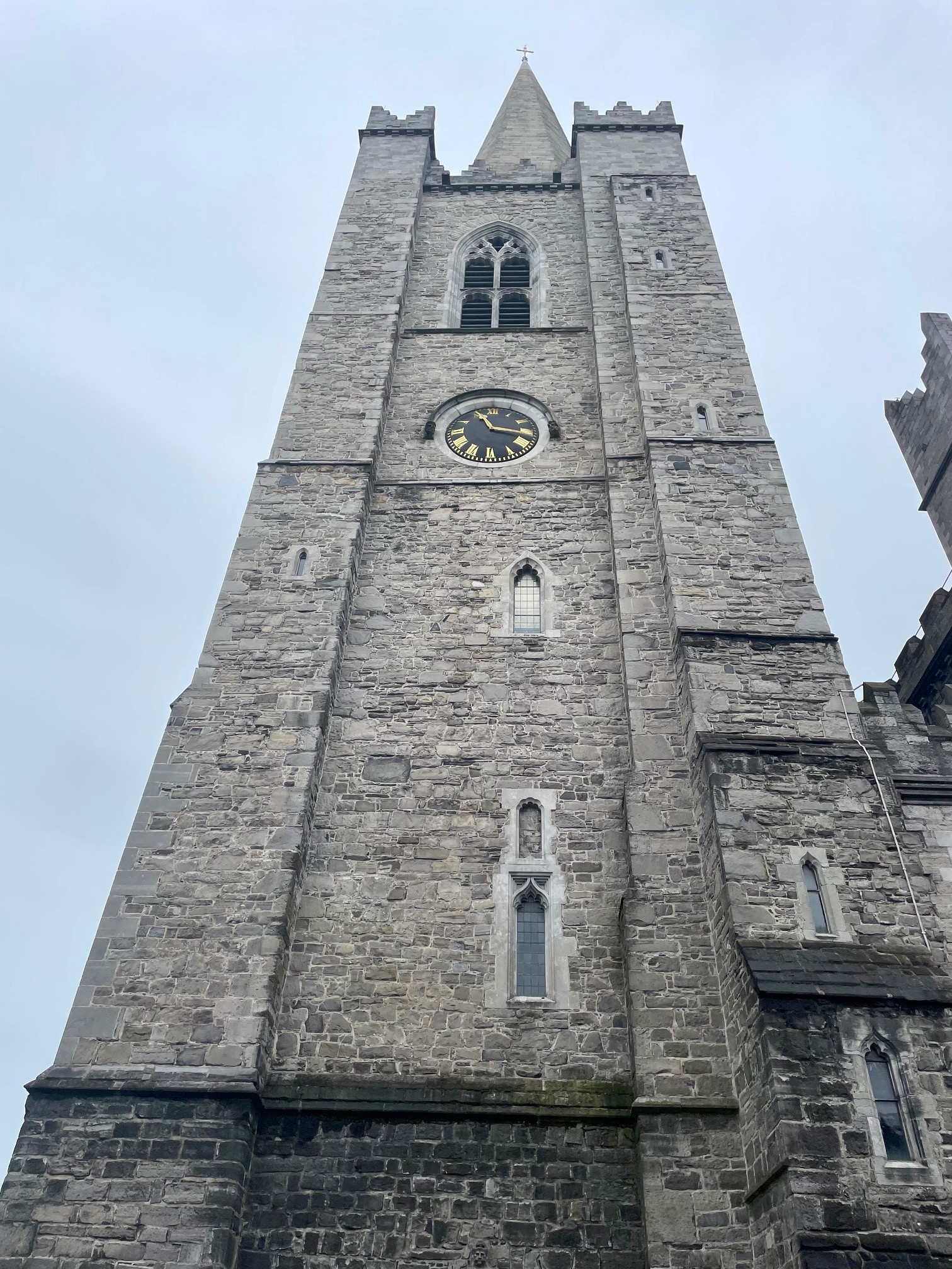
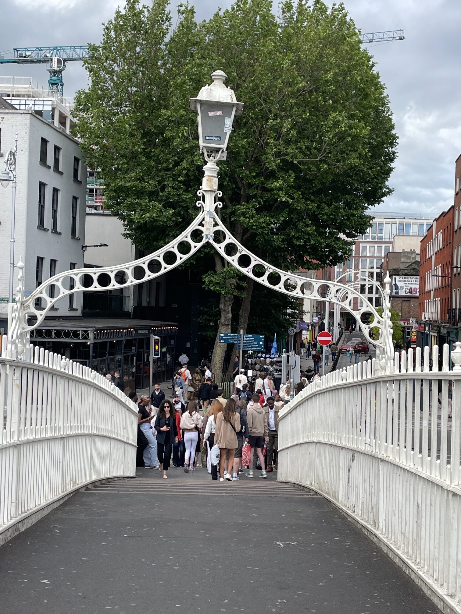
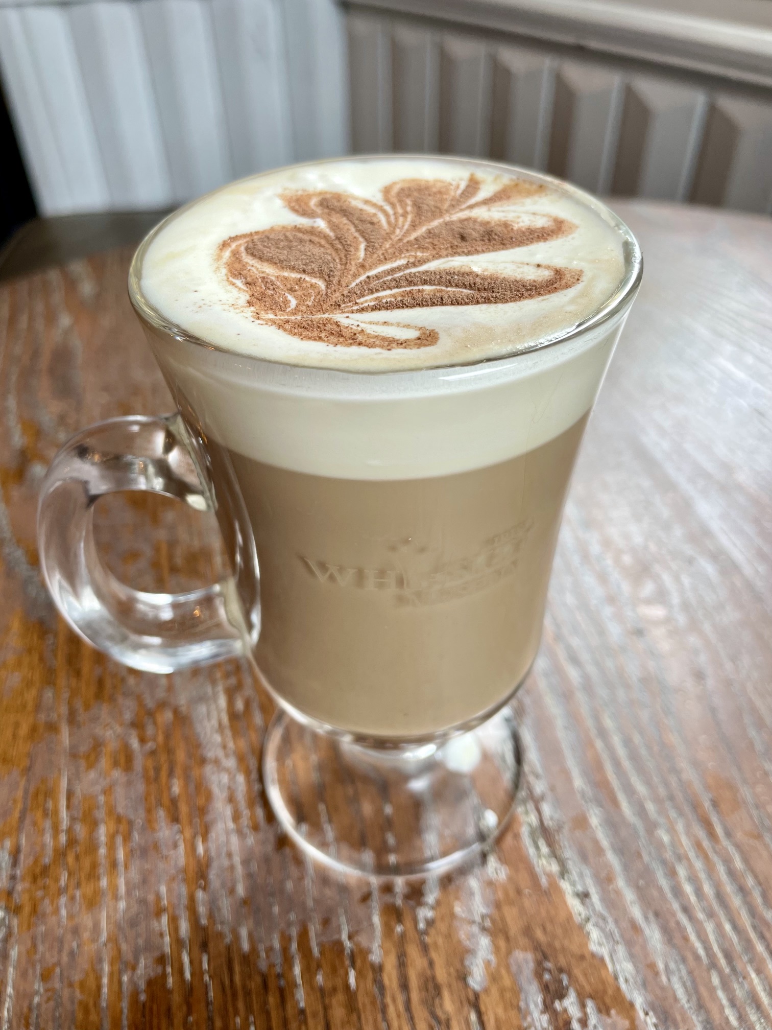
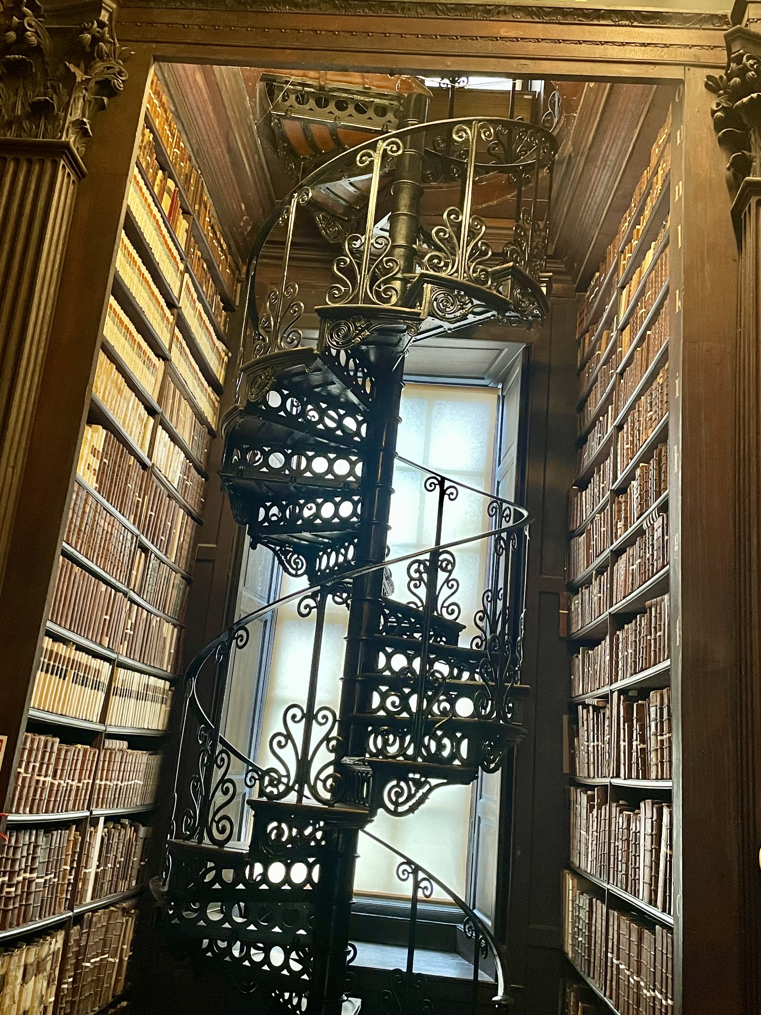
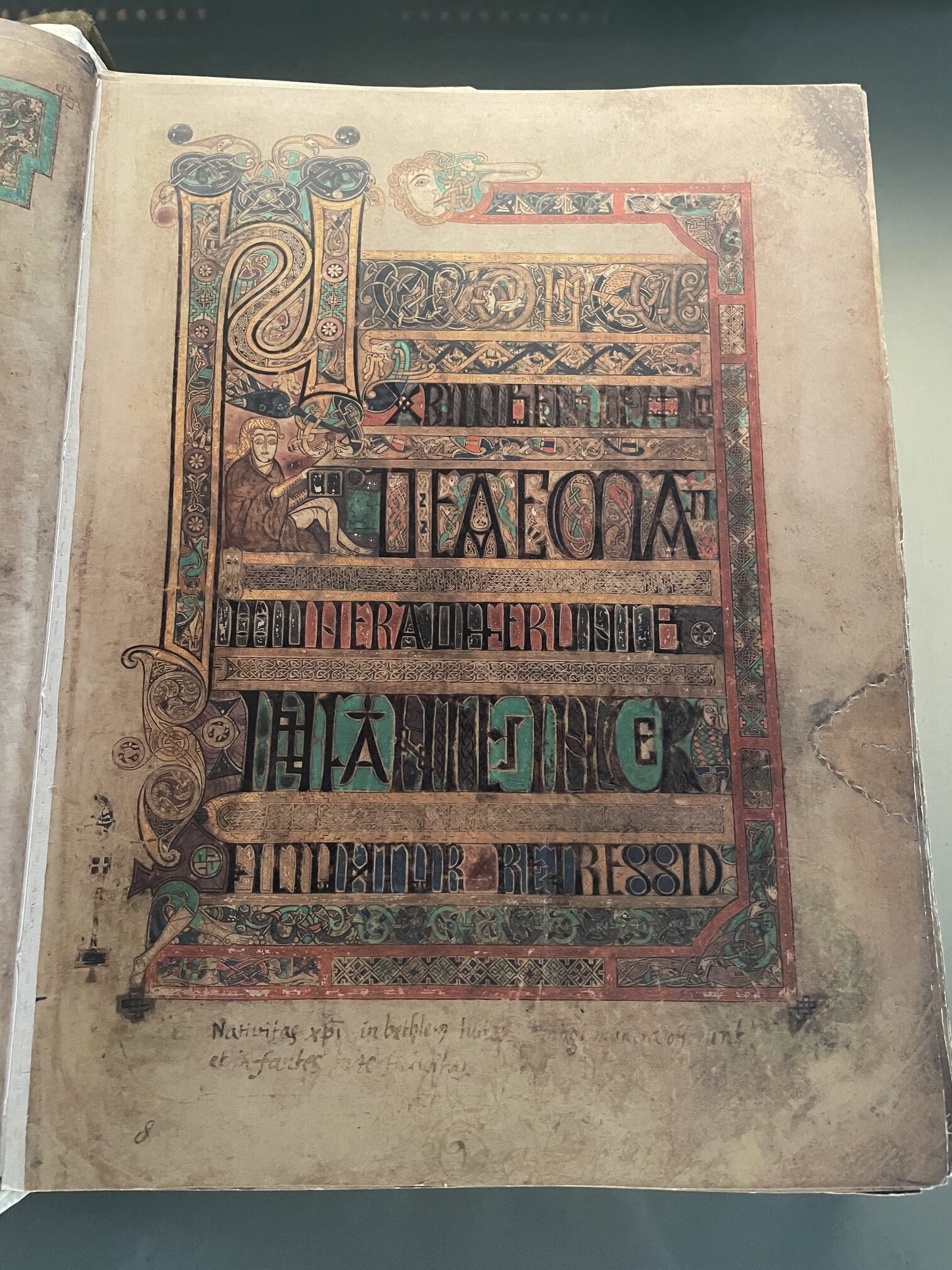
I took a train to Dublin and spent 2 days seeing the sites. The highlight was touring the Trinity College library to see the Book of Kells.
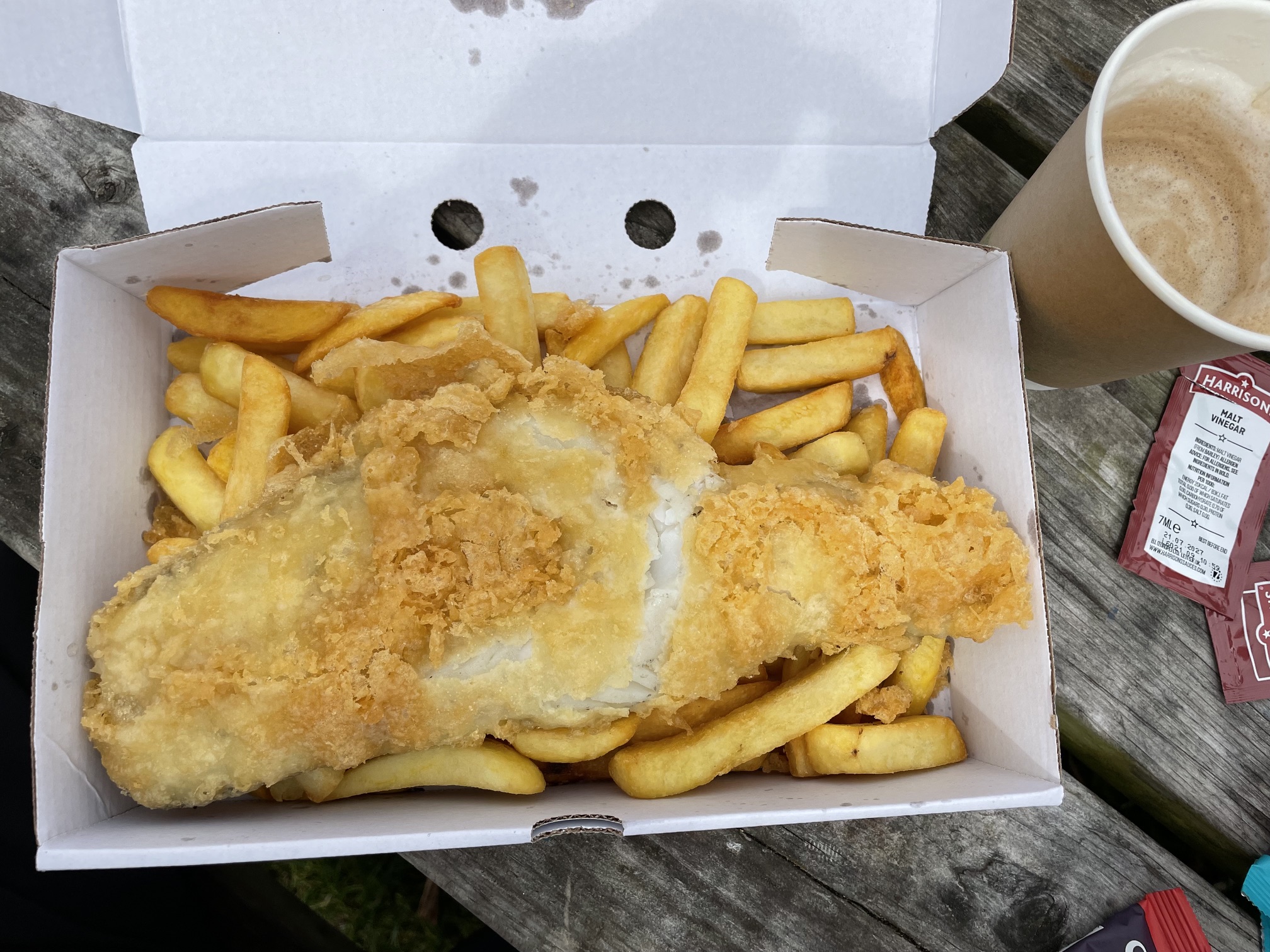
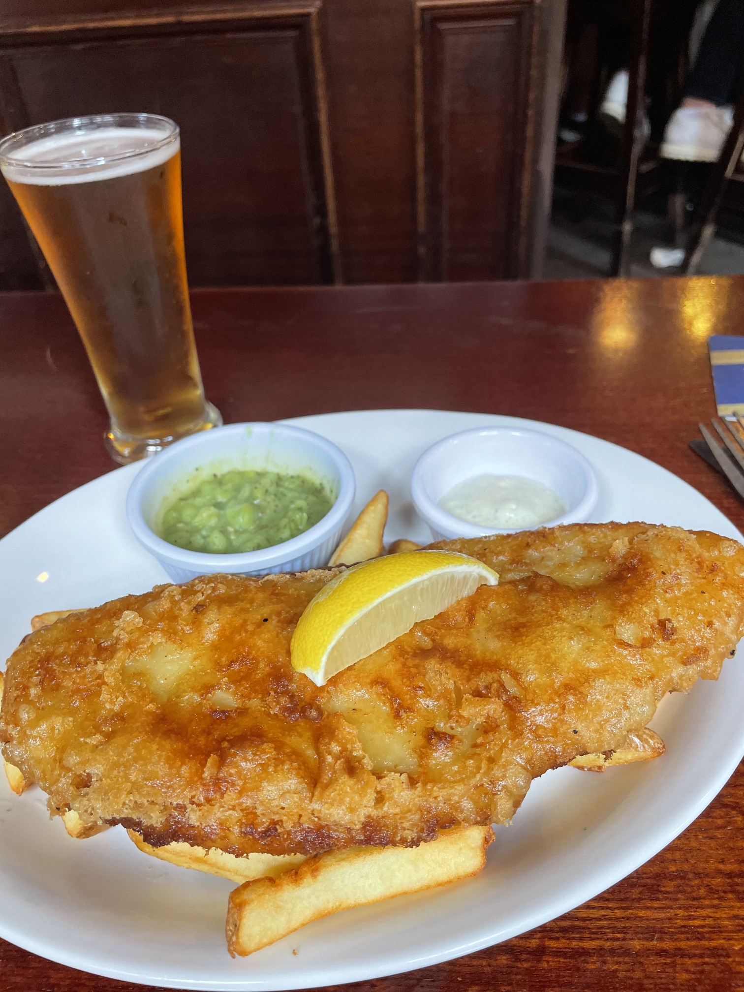
St Patrick’s CathedralHa ‘Penny BridgeFish & ChipsIrish CoffeeLast day in Dublin
Although my 20+ year old navigation electronics were all functioning, it was time to update to newer technology and features. While attending the Seattle Boat Show in February, I compared different brands and decided to go with the latest B&G (Navico) equipment for the chartplotter and radar.
Old Equipment
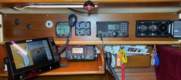
When I bought Apropos in 2004, most of the electronics were brand new (chartplotter, vhf, inverter/charger, autopilot, wind/speed/depth transducers & instruments). I added AIS, SSB, another chartplotter (Garmin 547XS) at the helm, and solar panels & controller in preparation for an offshore trip. More recently, I replaced the entire charging system with Victron equipment when I converted to Lithium (LiFePO4) batteries. But the Raymarine chartplotter & radar were still old and outdated equipment, although still working.
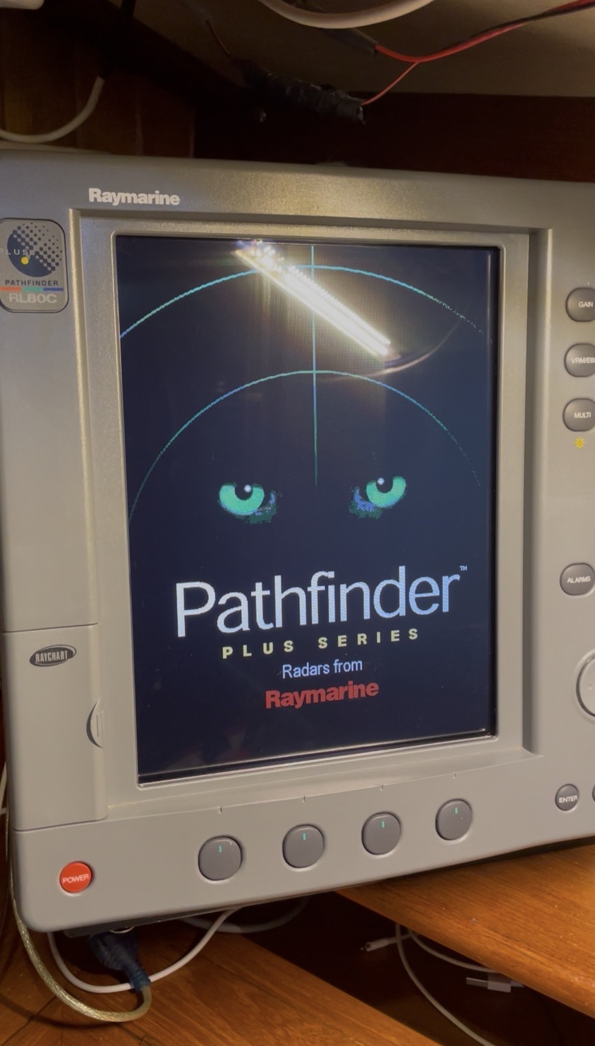
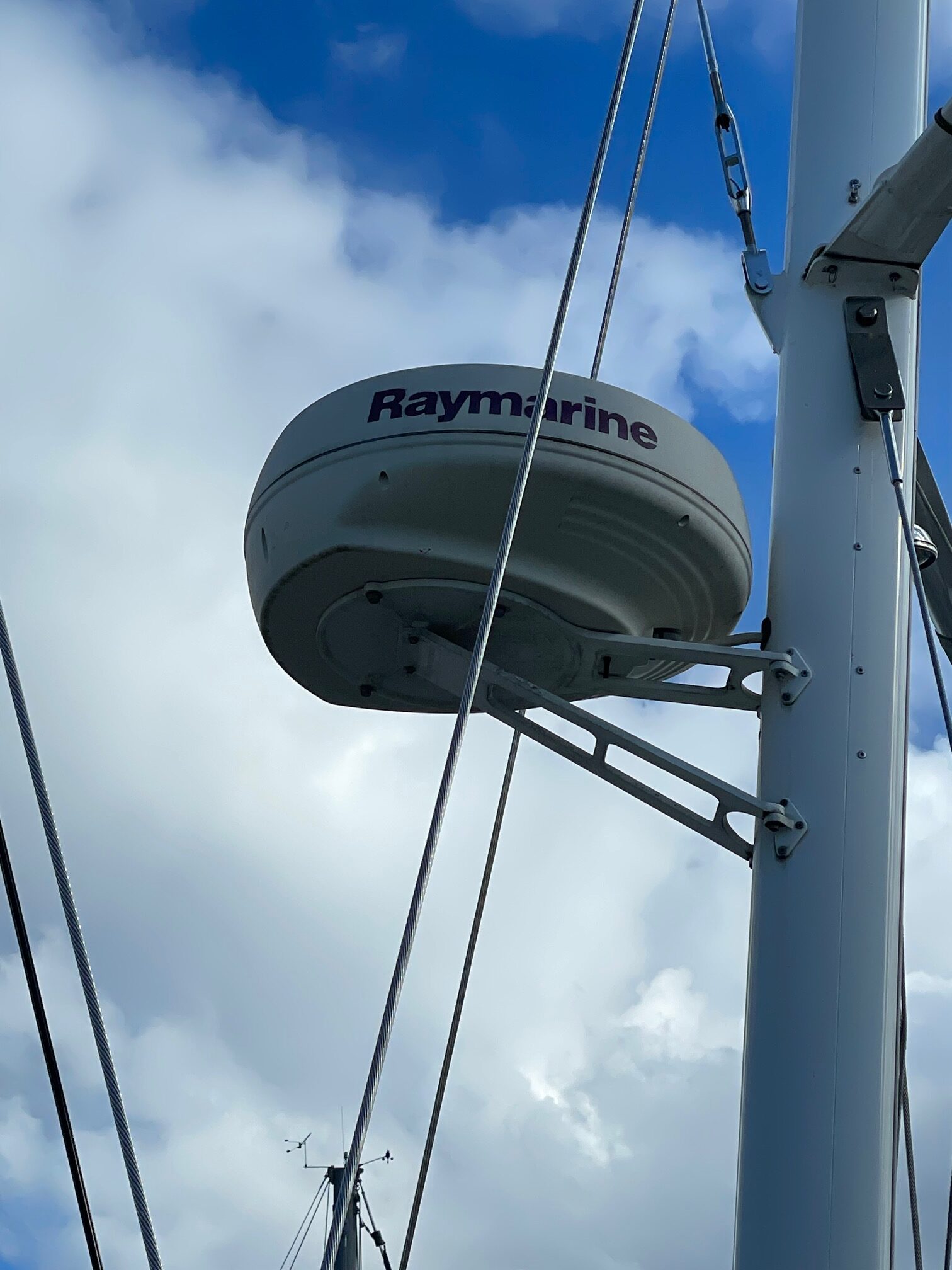
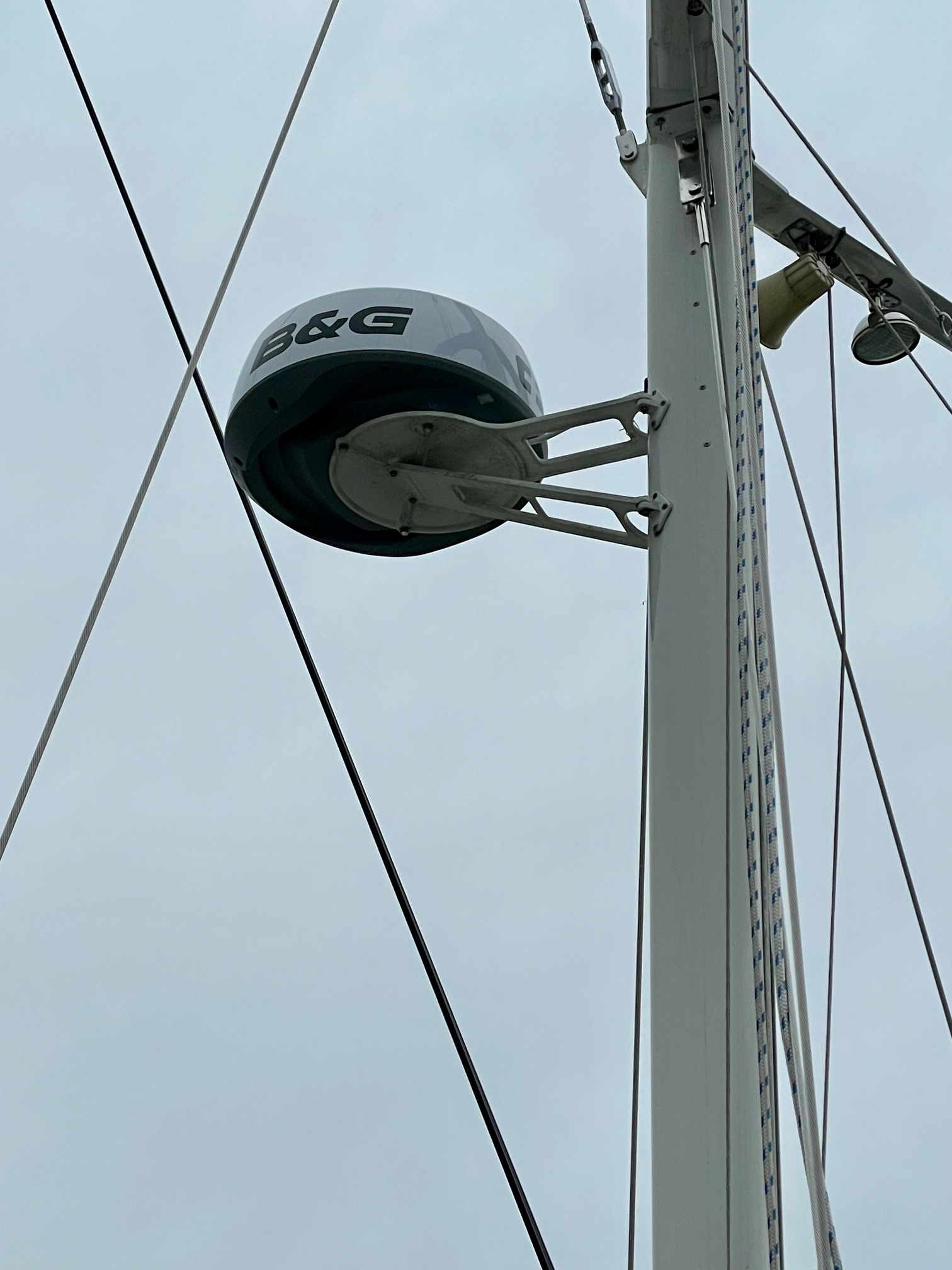
The Raymarine Pathfinder Plus (12″ screen) was mounted at the nav station and tied in with the Raymarine analog radar mounted on the mizzen mast. This system worked great for Puget Sound cruising especially in foggy conditions where the radar was our eyes. But we discovered when offshore that the radar was far too power hungry to run full time and even the chartplotter was seldom used since we had a smaller Garmin chartplotter at the helm.
Raymarine ChartplotterRadar
New Equipment
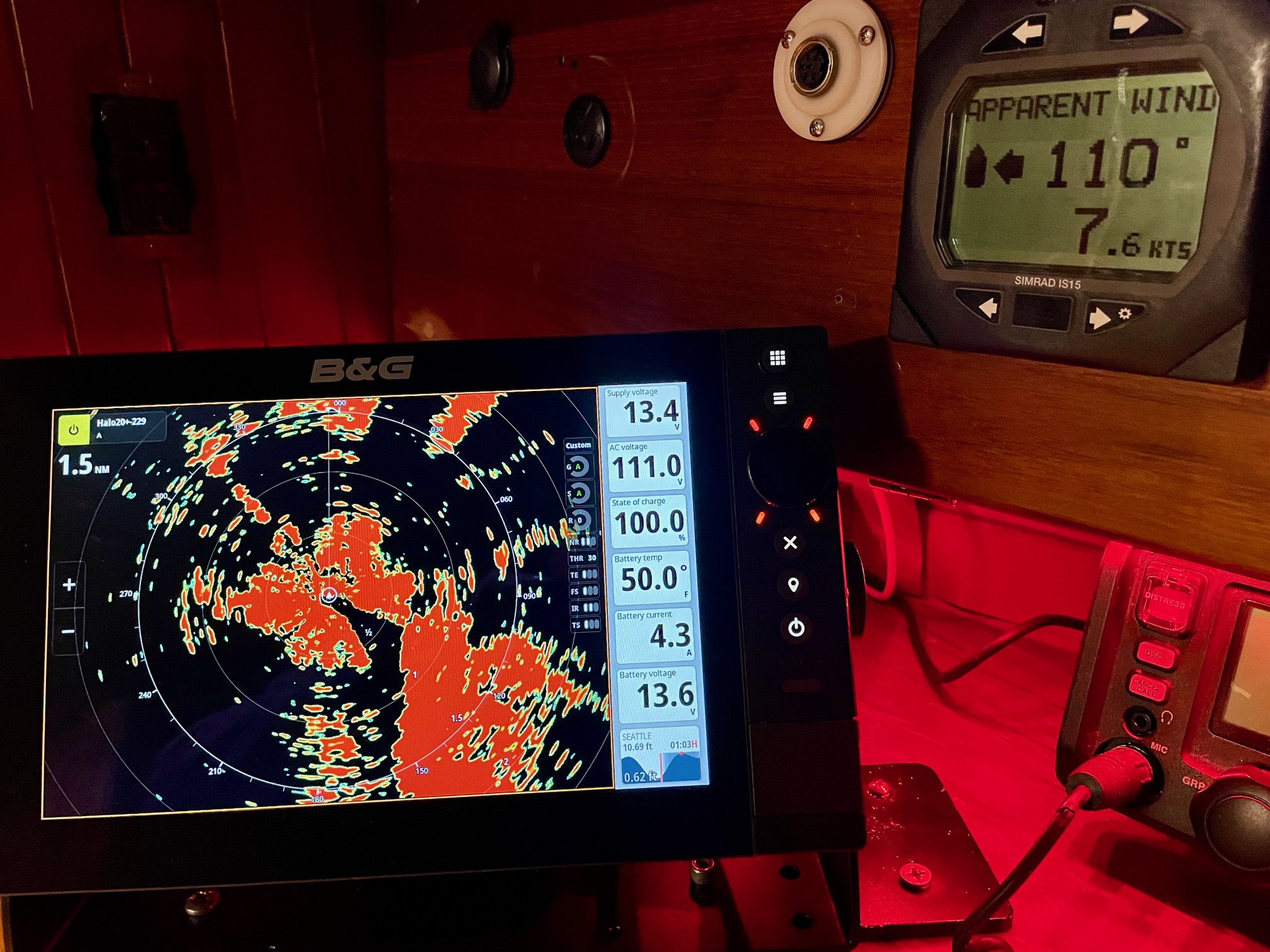
Besides updating for reliability reasons, I also wanted more features with the chartplotter and radar. I decided on the newest B&G chartplotter called Zeus SR paired with the B&G Halo20+ radar.
Zeus SR Features
High definition SolarMAX™ IPS touchscreen, viewable from all angles, even with polarised glasses
Separate modes for Cruising, Racing and Anchoring
Award-winning sailing features like SailSteer™, LayLines, Routes and StartLine
Compatible with C-MAP® DISCOVER® X and REVEAL® X charts
C-MAP®-powered Safety Alerts
Full integration with HALO® radars, B&G® Sailing Processors, Autopilots, Triton2 and Nemesis® instruments, wind sensors and more…
B&G® App integration with 12 months premium subscription when registering a C-MAP® X Chart.
Wi-Fi 5, Gigabit Ethernet & NMEA 2000® networking
Support for up to four IP video cameras
Set-up Wizard to get you up and running quickly.
Halo20+ Features
36 nm range from a compact 20-inch dome
Advanced pulse compression technology with beam sharpening
Simultaneous Dual Range operation sees both far and near
Ultra-fast 60 RPM operation at ranges up to 1.5 nm
VelocityTrack™ Doppler technology to avoid collision
Easy operation with harbour, offshore, weather and custom modes
MARPA target tracking (up to 10 targets, 20 in dual range)
Ready instantly from standby
Low power consumption
NMEA 0183 and NMEA 2000
Before installing these pieces of equipment, I had to make a big change to the boats’ communication network. Boats like Apropos built in the 1980’s used the NMEA 0183 standard. NMEA 0183 is an ASCII-based serial communication protocol used to connect marine electronics–such as GPS, depth sounders, autopilots, and chartplotters–allowing them to share navigation data. It uses a “single talker, multiple listener model.”
NMEA 2000 (N2K) is a standardized, high-speed digital network for marine electronics, based on the CAN bus protocol used in automobiles. It connects multiple sensors (GPS, wind, speed, depth, battery, engine) to displays, allowing data sharing across brands. Key benefits include easy “plug-and-play” installation, reliability, and real-time, bi-directional communication among devices.
Since Apropos’ sensors (depth sounder, speed, rudder position) and 5 display instruments are all NMEA 0183 devices, I decided to go with a hybrid system that retains some 0183 devices but adds NMEA 2000 capability for new equipment that supports only NMEA 2000. As my old 0183 equipment (AIS, VHF, sensors, display devices) fails, it will be easy to buy the new 2000 version and simply plug it in.
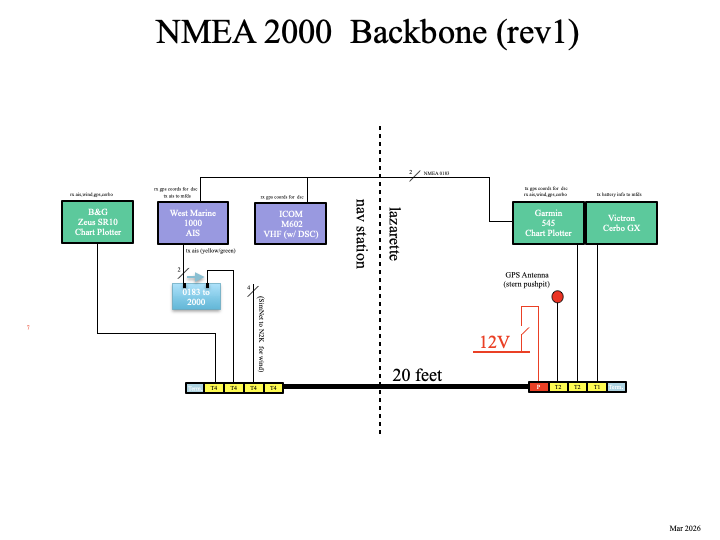
What’s meant by “plug-and-play”? An N2K system has a backbone, which is a 5 conductor wire that runs throughout the boat and can easily be extended as needed. It has a 120 Ohm terminator on each end, a power T-connector anywhere along the backbone for supplying 12V power, T-connectors which are used to connect individual devices to the backbone, and drop cables, which are short cables (6 meters max) connecting devices to the T-connectors. Here is a diagram of Apropos N2K backbone (the backbone is the thick black line, the power T is red, the T-connectors are yellow, the terminators are light blue, the green boxes are NMEA 2000 equipment, and the purple boxes are NMEA 0183 equipment).
A dalemma exists when you want to display information that comes from NMEA 0183 equipment on N2K equipment. In my case, I want to see the AIS (Automatic Identification System that tracks other vessels and lets them see you) output on the Zeus chartplotter. Since the AIS puts out 0183 data and the chartplotter accepts 2000 data, a piece of equipment called a Gateway can be used that converts 0183 to 2000 and vice versa. This is shown in the above diagram with the light blue box.
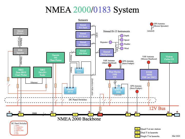
Here’s another diagram that shows more detail of the NMEA 2000/0183 System on Apropos (the green boxes are NMEA 2000 devices and the purple boxes are NMEA 0183 devices).
IP Cam 1
I wanted a camera with video to help keep watch since I often single hand Apropos. In open ocean sailing, going below deck for 5 minutes is no big deal, but in Puget Sound, I seldom go below deck for more than a minute unless someone else is standing watch. Last summer I tried using a GoPro camera mounted on the bowsprit. I could view the video on an iPhone or iPad, but several problems made it almost useless. The biggest issue was losing connection. The WiFi signal just wasn’t reliable from the bow to the cockpit and there was no signal when going below deck, where it would be most useful. Also, the battery life of the GoPro would only last an hour or so unless I shut it down, and powering it back up whenever I wanted to use it was time consuming. So when I started looking at new chartplotters, I discovered the SimRad IP Cam 1. Here are the main features:
Simple setup with B&G Zeus multifunction displays
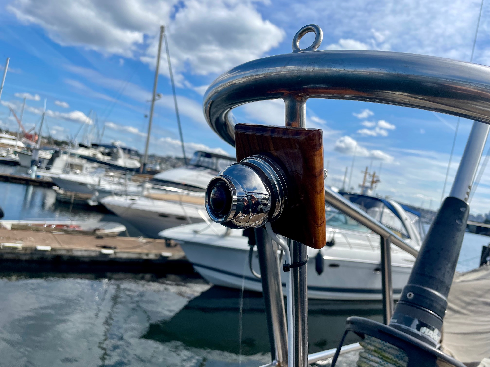
Rugged 316 stainless steel construction designed to withstand saltwater environments
1920 x 1080 Resolution
Night time and dark area operation high performance IR LEDs (10m range)
1.8mm wide-angle lens
Power Over Ethernet (POE) or 12V supply options
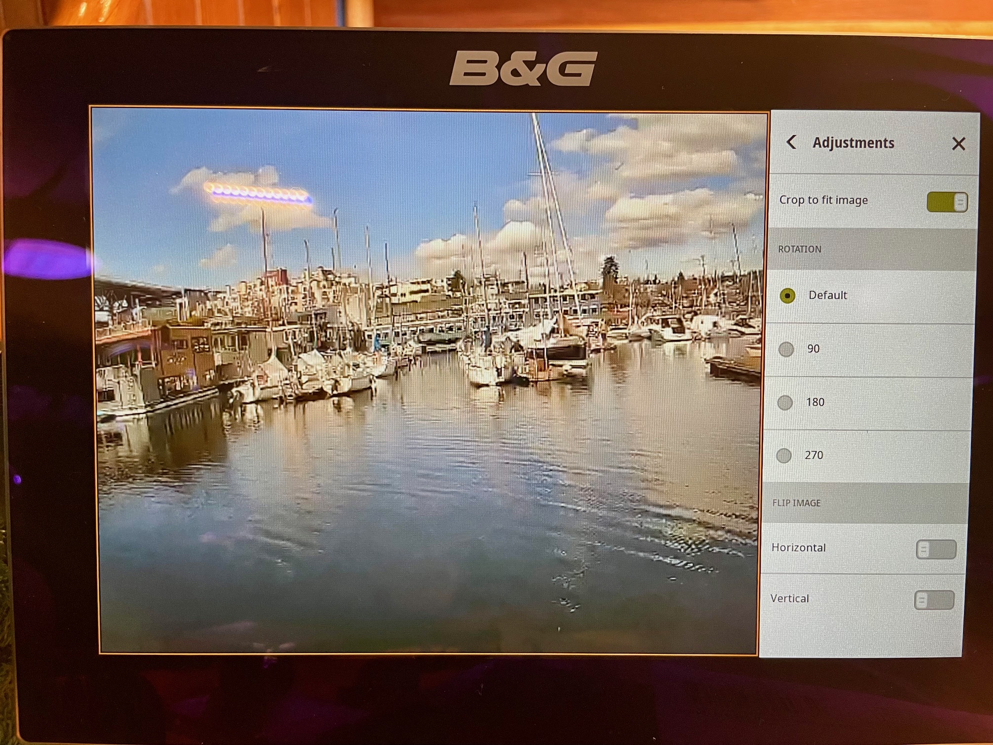
I connected it using Power Over Ethernet (POE) with a switched power connection so I could toggle it on and off from the nav station. I ran the CAT7 Ethernet cable to the bow and mounted the camera to a piece of teak, and attached it to the bow railing. I’ll see how this works and will also consider mounting another camera on the main mast around spreader height (the downside is having the view partially blocked by the headsail when sailing). To use it, I just open the App on the Zeus chartplotter and select the camera.
IP Camera Video on Chart PlotterIP Camera
Misc.
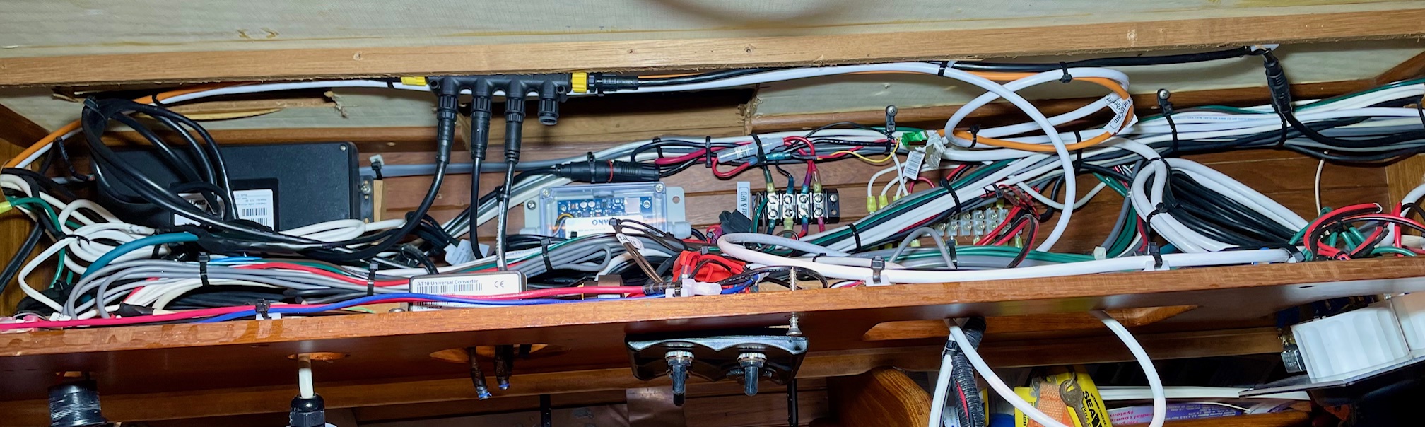
Something additional I did was to make access to the navigation station wiring bay easier. Previously, I had to undo 10 screws then pull out the panel that has equipment mounted on it and lots of wiring behind it. This made working on the panel and the wiring behind it difficult because there was nothing to support the panel. So to make it easier, I added hinges along the bottom of the panel to allow it to pivot down to expose the back of the equipment and the wiring behind it. The top is now fastened by just 5 screws. I hid the unused screw holes along the bottom with teak plugs and added wood trim around the outside edges to make it look better. I moved things around the panel and added an audible alarm (tied into the chartplotter for when the radar finds a dangerous target), added 3 switches–one for turning on the IP camera, one for turning on accent lighting, and one currently unused, added another DC outlet for USB charging, and refinished the panel with 4 coats of satin varnish. I also did a major clean-up of the wiring and added labels.
Wiring behind Nav Station panel
It took about a full month working full time to create the N2K backbone, remove the old equipment and wiring, install the new equipment, and tidy up all the wiring.
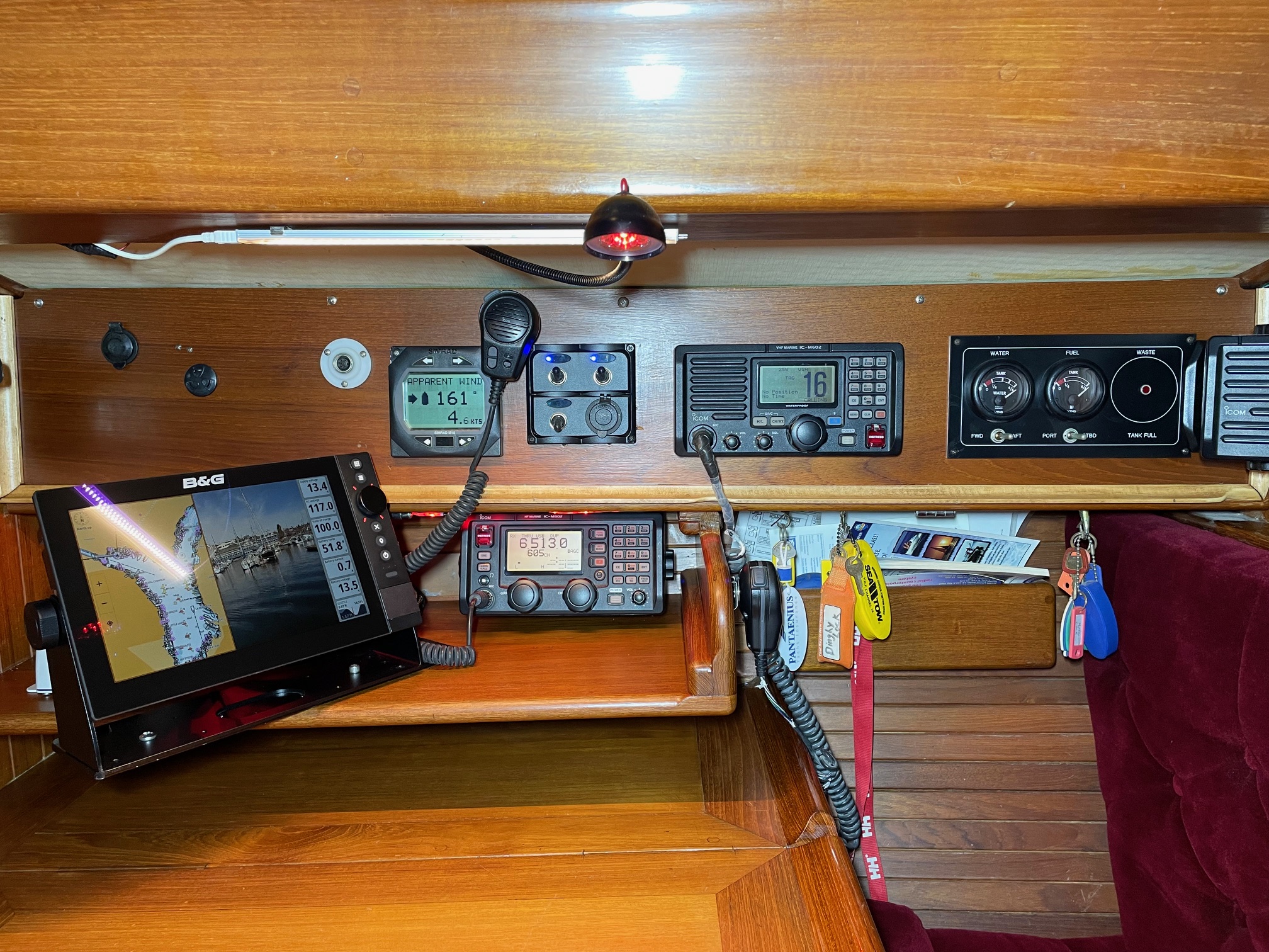
Here are some pictures of the completed work.
Nav StationNew Radar on Mizzen MastRadar on Chart Plotter
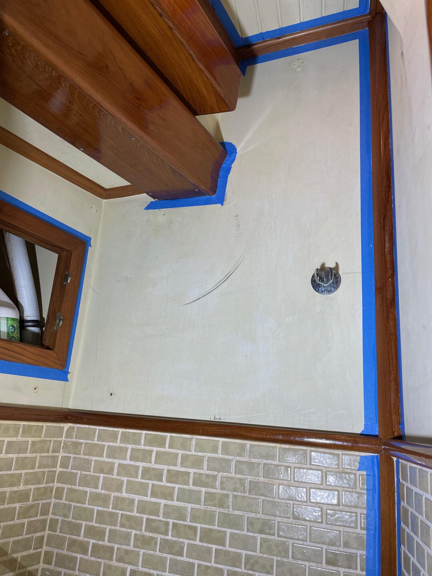
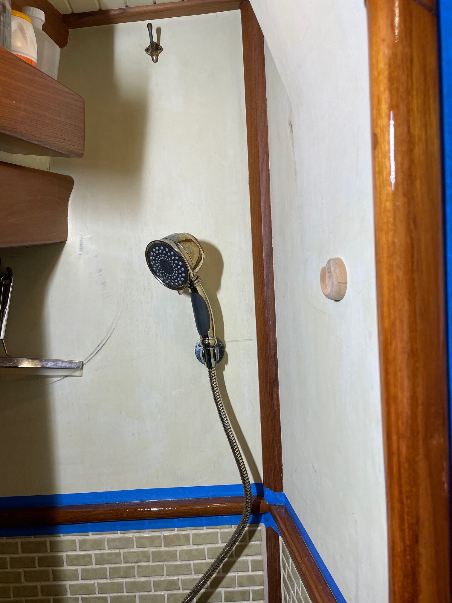
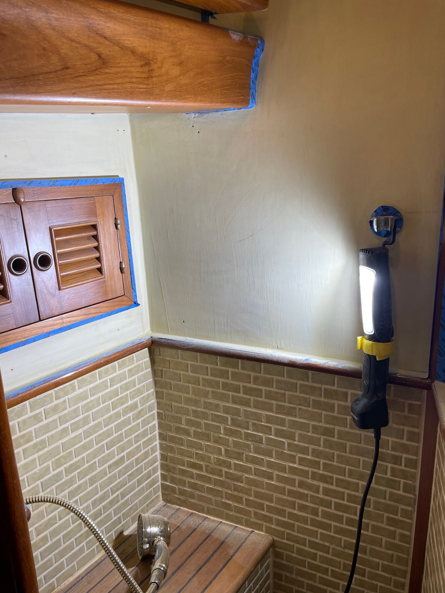
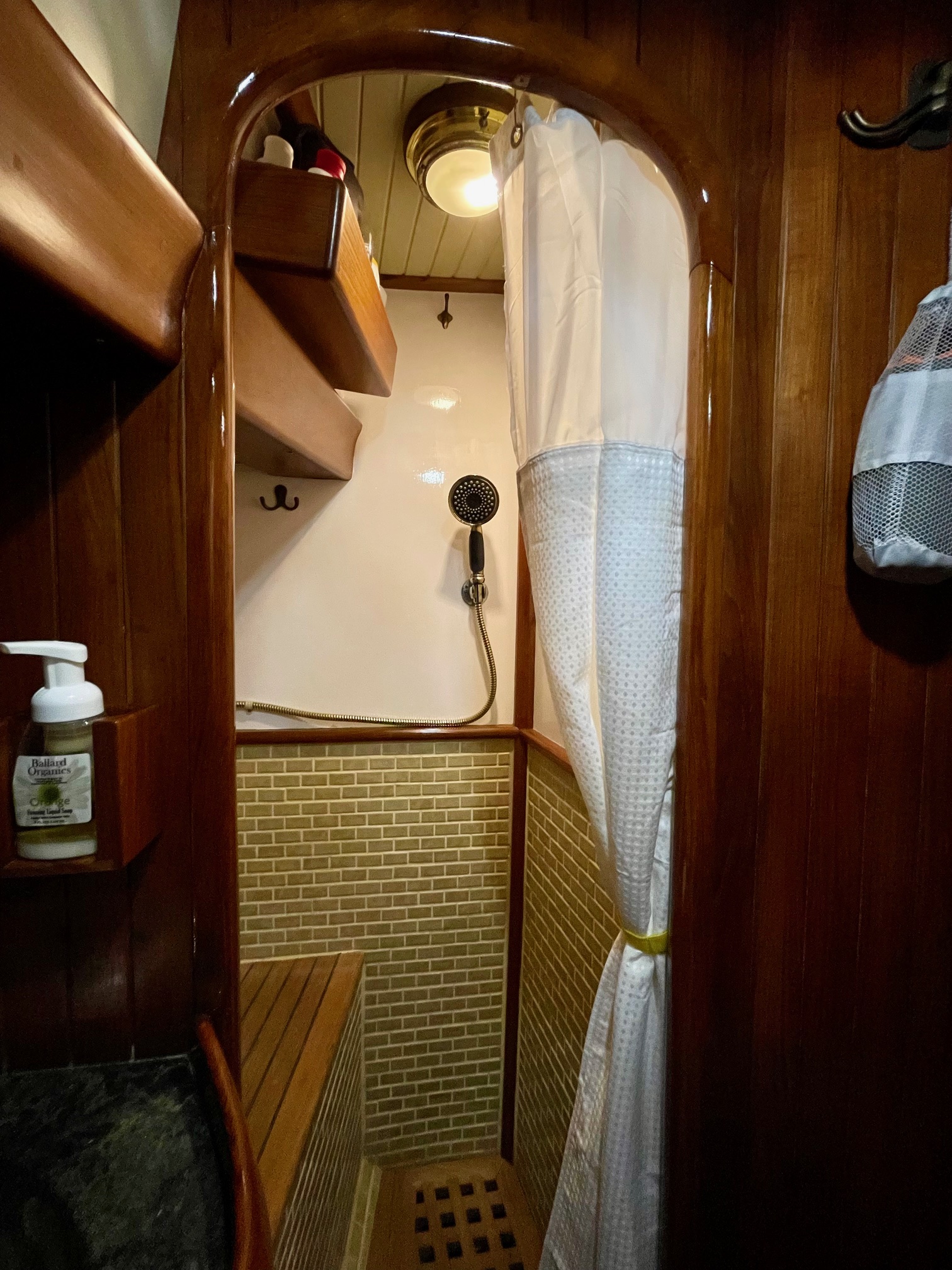
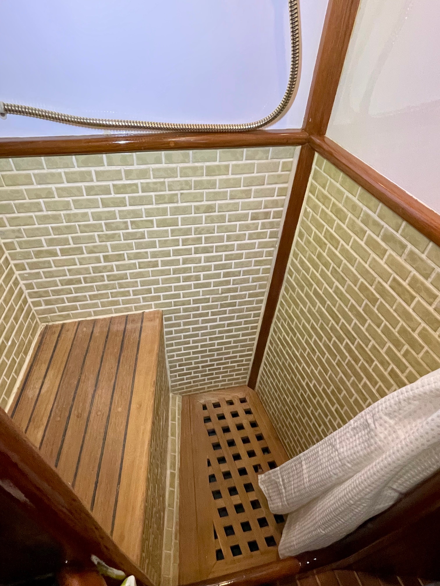
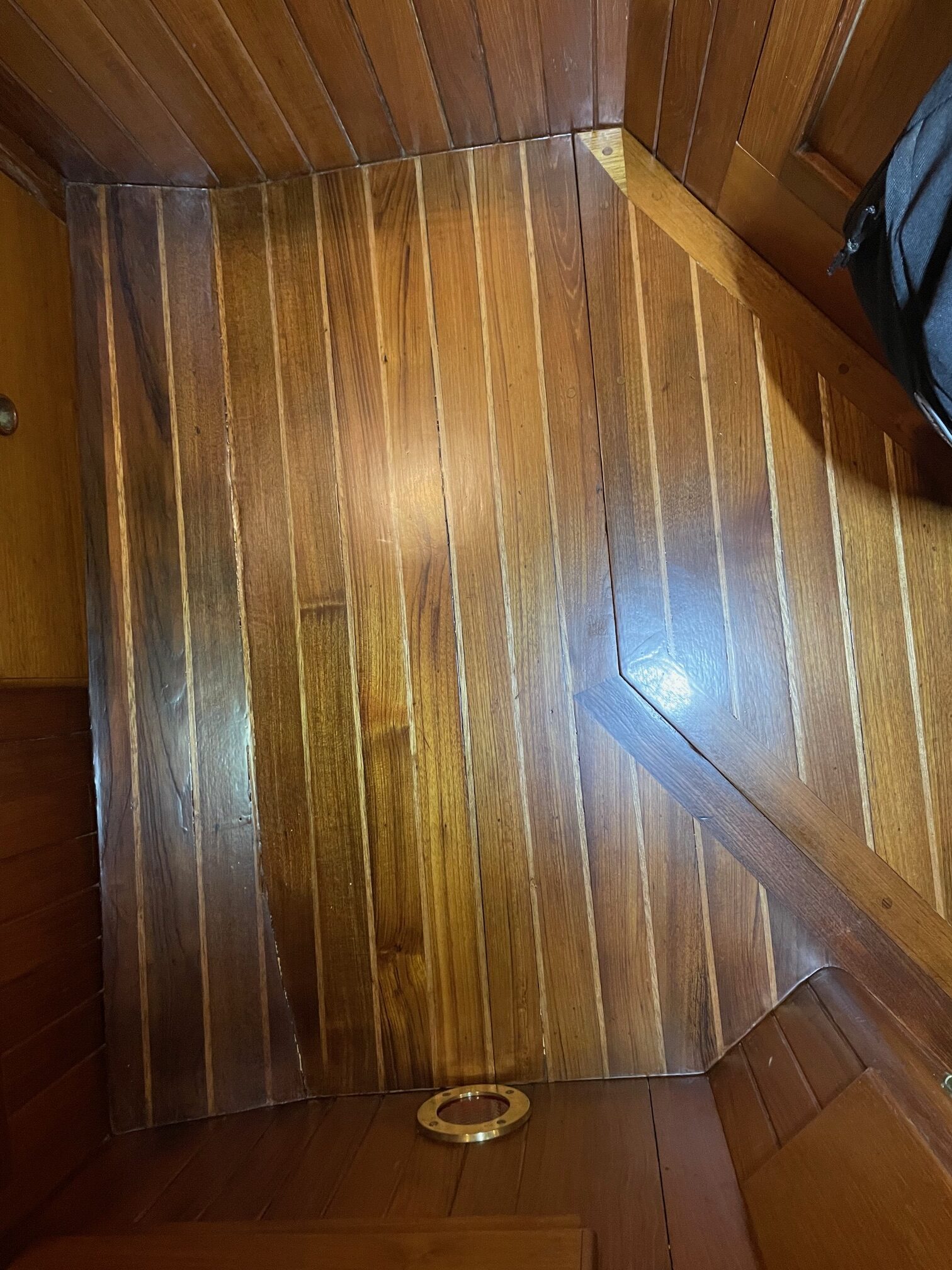
Apropos has a nice separate shower stall (some boats have a wet head that combine the shower with the rest of the bathroom). The floor has a teak grating with a water tight compartment below it that gets pumped overboard automatically using a float switch to power a pump. The lower sections of the shower walls are tiled and the upper sections painted, with teak trim between. A seating bench has teak decking with caulk, matching the outside teak decks. Teak doors open to a small storage cabinet, and above that it is a teak shelf.
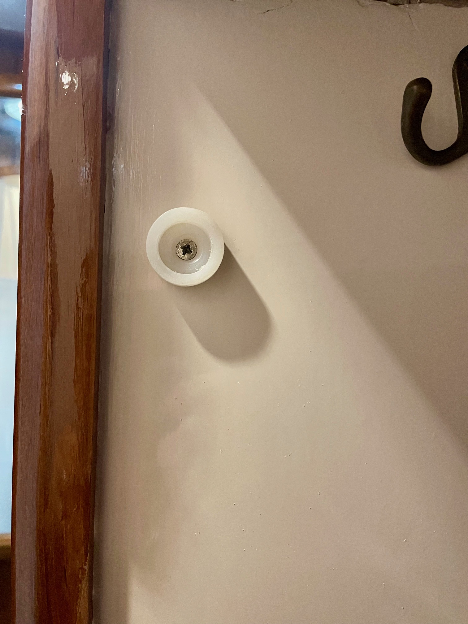
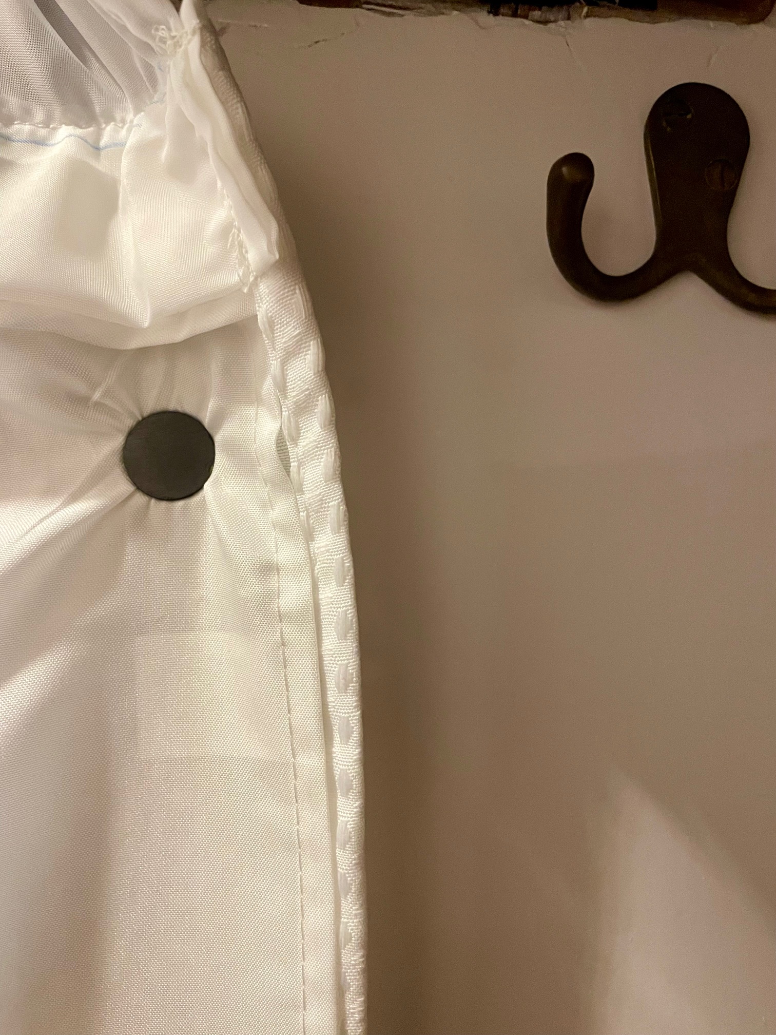
The main objective was to repaint the walls. The paint was most likely original and after over 40 years, was wearing thin and had lots of scuffs & scratches. I decided to first varnish the teak with 4 coats of Petit Flagship satin, then mask the teak to paint the walls. I used a special epoxy high-gloss paint for the walls. This paint is made for wet areas and can even be used for underwater. Four coats were required to get a nice even finish with a light sanding between coats. I cleaned the teak grating and seating area then coated with Semco. A new shower curtain needed to be custom sewn to shorten the length and I improved the curtain rail attachments. Lastly, I made 6 magnetic curtain holders (3 per side) to keep it closed during showers.
Satin VarnishHigh Gloss VarnishSanding the wallsFinishedSemco on seating and gratingCurtain holder (1 of 6)Curtain holder magnet
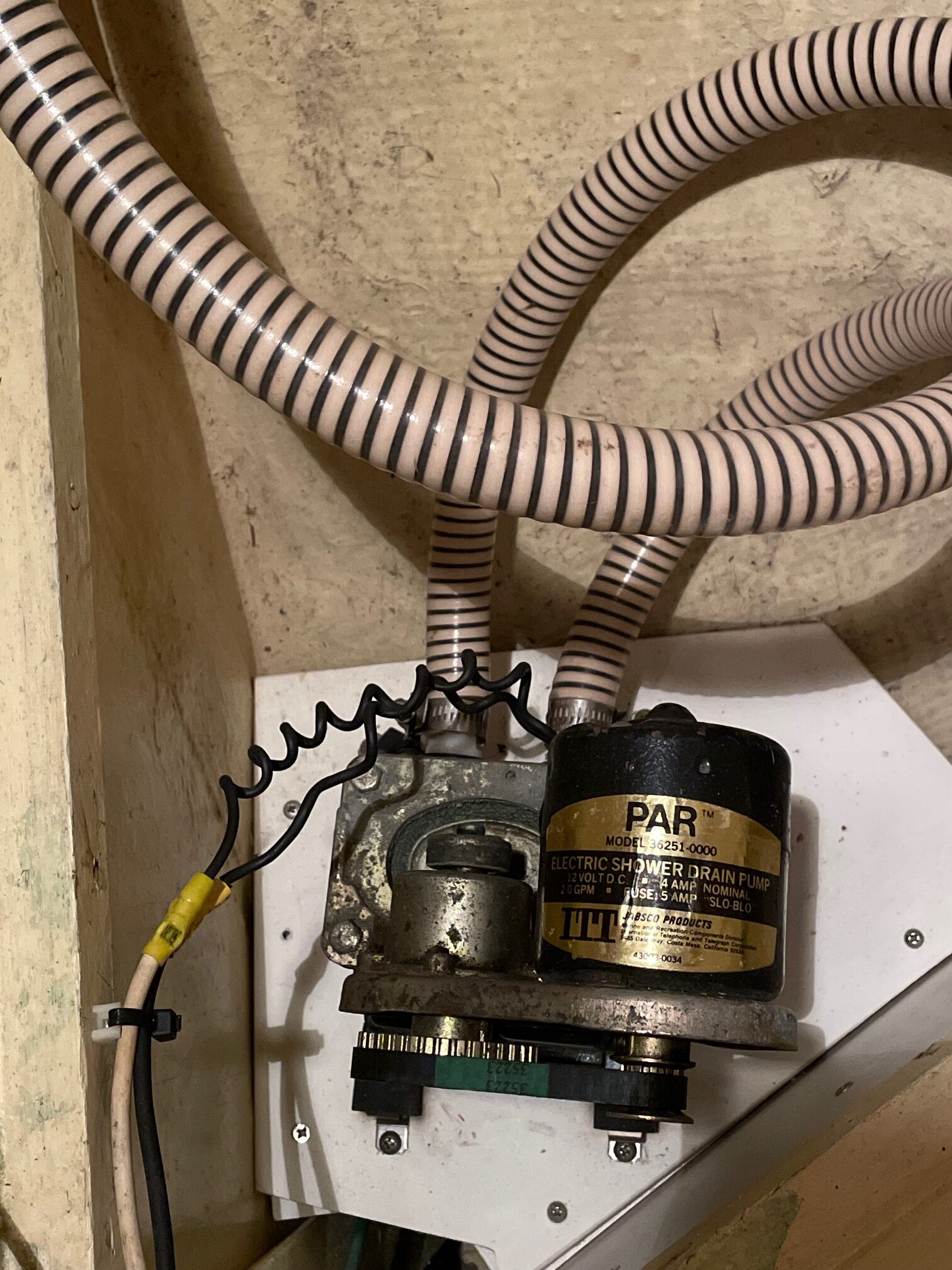
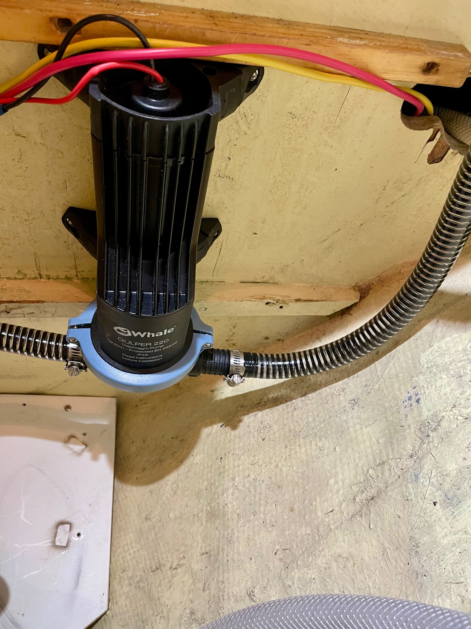
The pump used to pump the shower water overboard was an original Jabsco Par belt-driven diaphram pump (43 years old!). Apropos had 3 of these pumps (bilge, fresh water, shower) on board and they worked very well for many years. I used to carry re-build kits aboard and have rebuilt them. But there are more modern pumps available now that use less power and are higher performance. I replaced the hoses and pump with a Whale Gulper 220.
Old pumpNew pump
More Interior Varnish
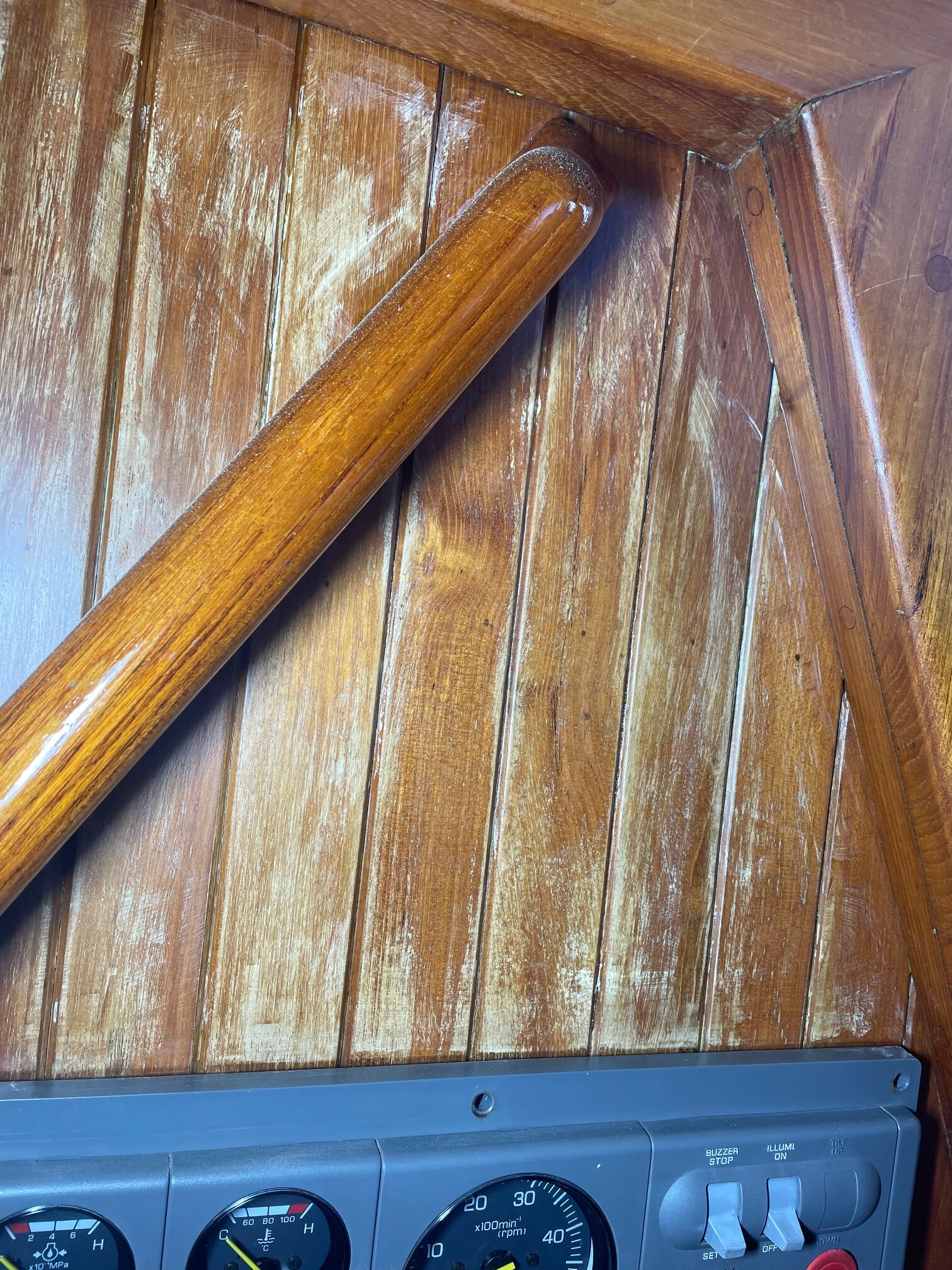
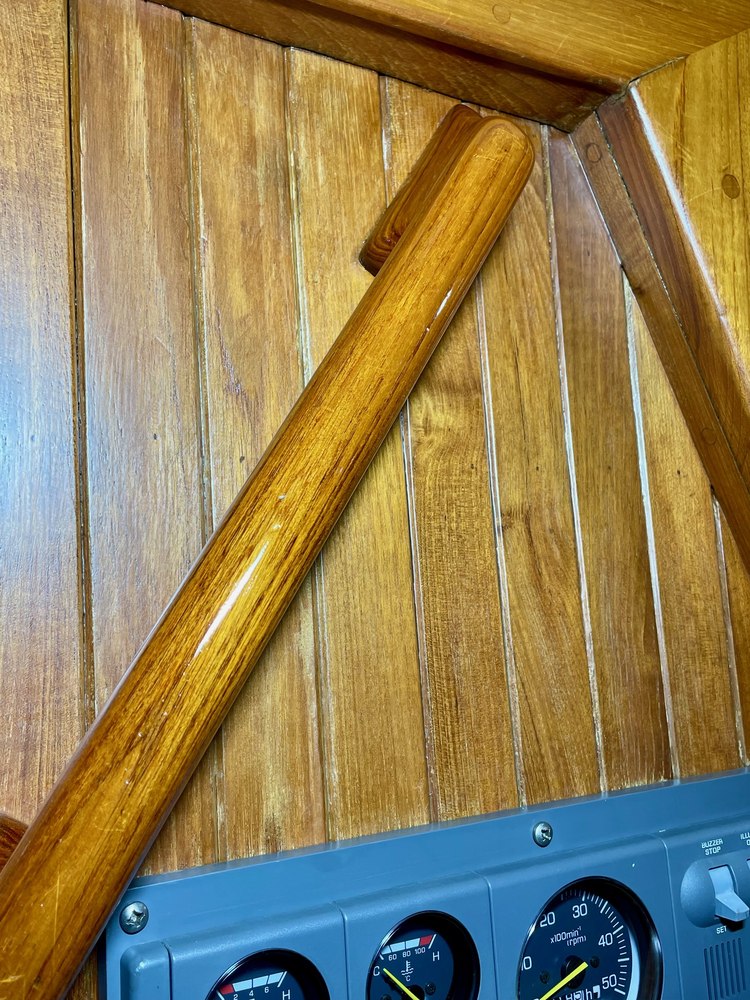
I continued with varnishing the cabin teak that I started a year ago. The teak panels just inside the companionway (both sides of the steps) were the most worn due to UV exposure when the hatch is open. Both sides required heating & scraping the old varnish to get down to bare wood, then sanded for a more even coloring. I applied 4 coats of satin varnish to the vertical planks and 4 coats of high gloss varnish to the 2 grab-rails. Here are the before and after pics.
BeforeAfter
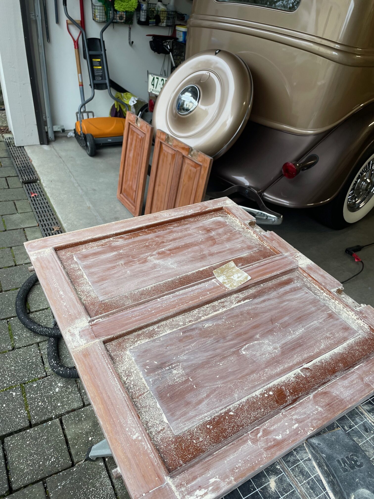
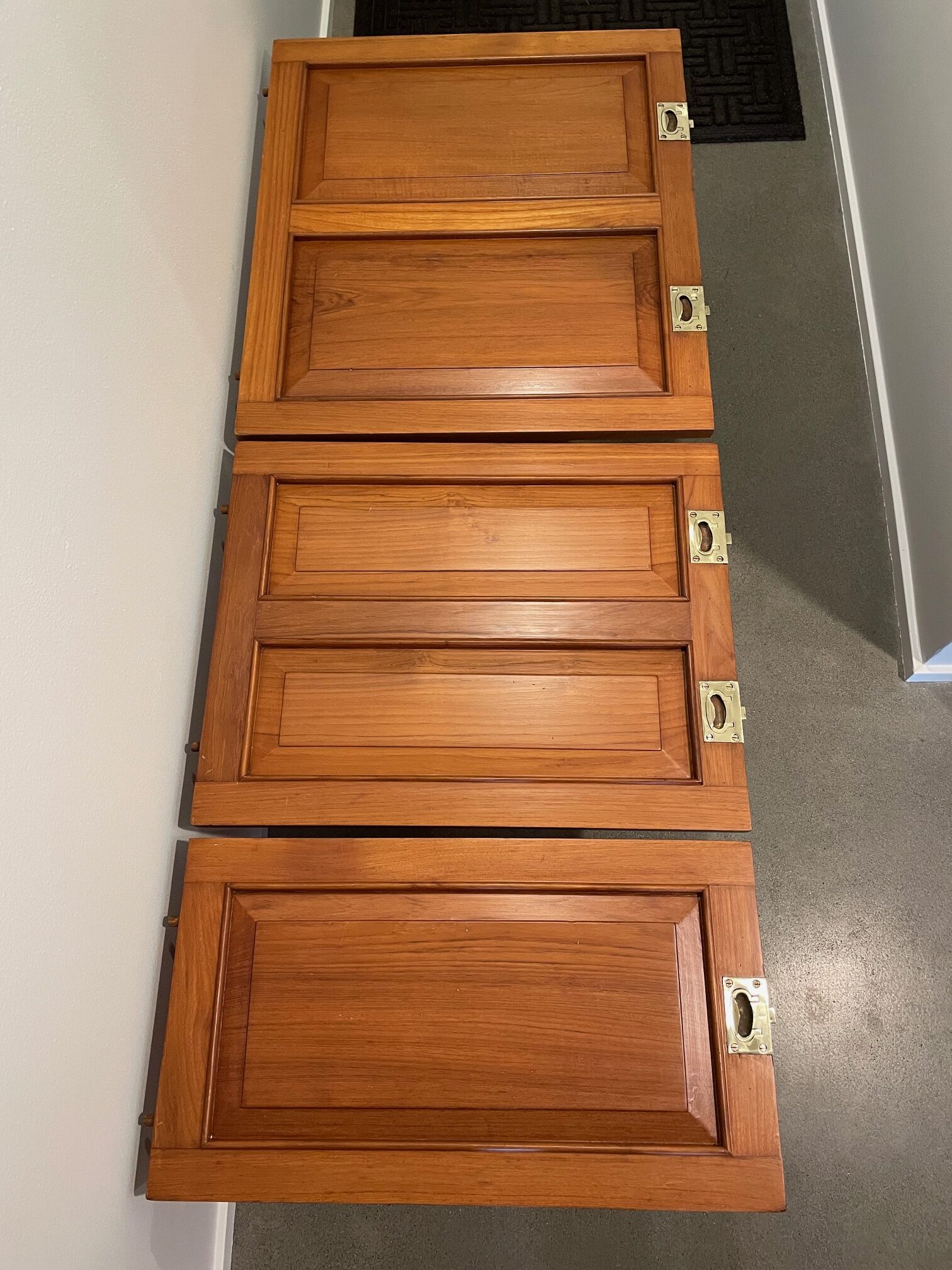
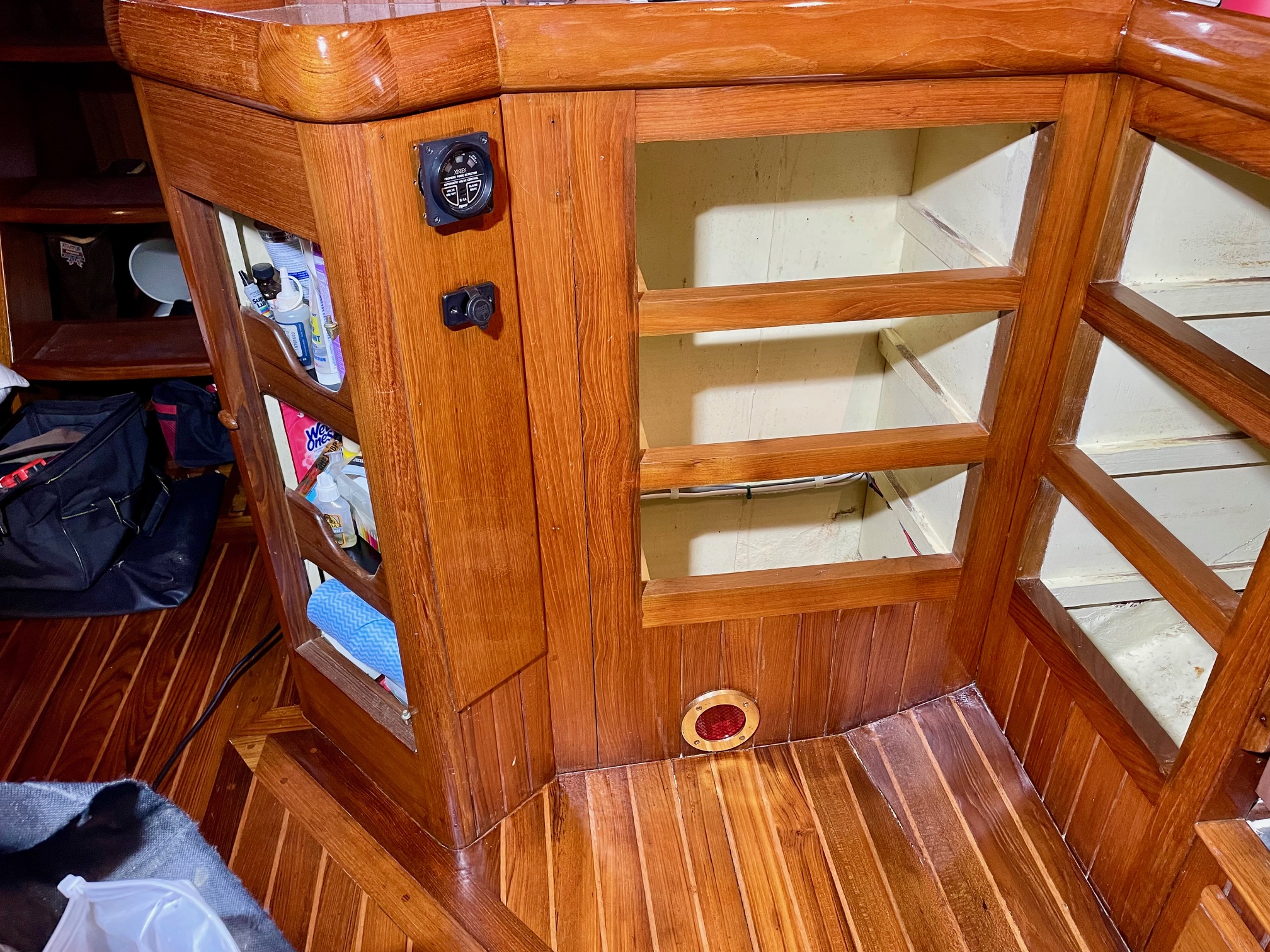
I removed the panels in the galley that enclose the engine bay to bring them home for refinishing. First I removed the hardware, then sanded with 80 grit followed by 240 grit sandpaper, followed by 4 coats of Petit Flagship Varnish in satin. I polished the hardware and coated with ProtectaSeal, something I’ve been doing with interior brass and bronze parts for years. The teak frame that holds these panels was refinished on the boat.
SandingFinished
I’ll continue varnishing the interior throughout the winter until my spring projects take over. This spring/summer it’s time for another haul-out where I’ll re-paint the bottom, replace the cutlass bearing, replace the shaft seal, and service the Maxprop propellor. This is the last major work to get Apropos ready for her next big cruise.
In 20 years owning Apropos, we’ve anchored hundreds of times. Bringing the anchor back up requires someone down below in the v-berth stacking the chain and a person on-deck operating the windlass. The two need to communicate because the windlass can operate faster than the person below can stack the chain. Sometimes I do both jobs by going back and forth–operating the windlass to bring in 20′ of chain, going down below to stack, then going back on deck and bringing in another 20′, and so on. Pulling in a muddy chain slows down the process because the person on deck working the windlass is also washing the mud off the chain links with the wash-down deck hose.
I’ve always wanted to improve the anchoring procedure, and finally came up with a solution while visiting another Hans Christian 43.
But first, let me explain why a person is needed to stack the chain down below.
Old Configuration
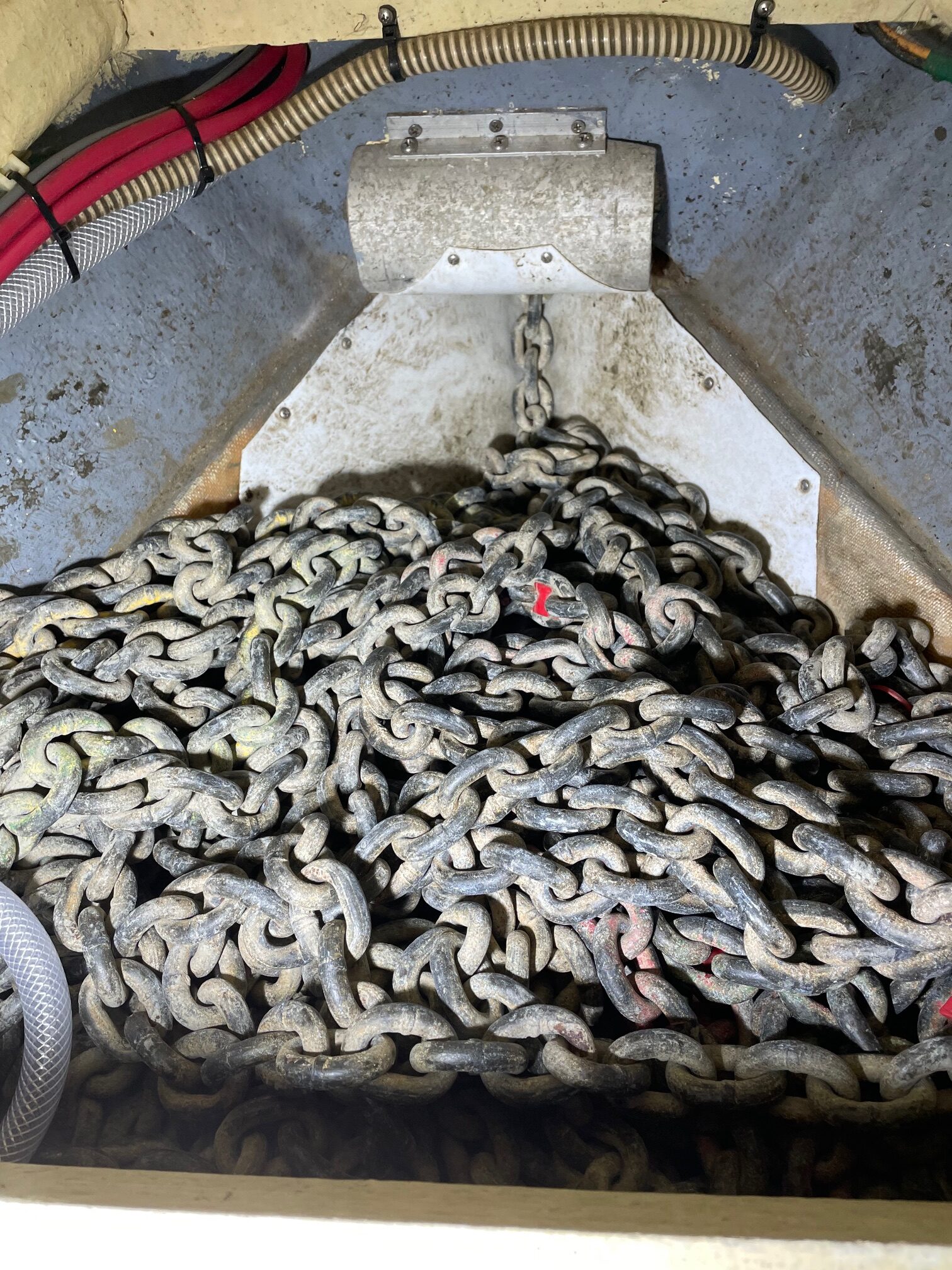
Apropos has 2 anchors on the bow–a primary anchor (65 lb CQR) with 300′ of 3/8″ chain, and a secondary anchor (45 lb CQR) with 300′ of 3-strand 1/2″ rope. The chain is stored in a lower locker located under the v-berth bunk. The rope is stored in an upper locker located forward of the v-berth. A 4″ diameter aluminum hawse pipe passes through the upper locker and feeds the chain to the lower locker.
Lower Locker with 300′ 3/8″ ChainUpper Locker with 300′ 3-Strand Rope
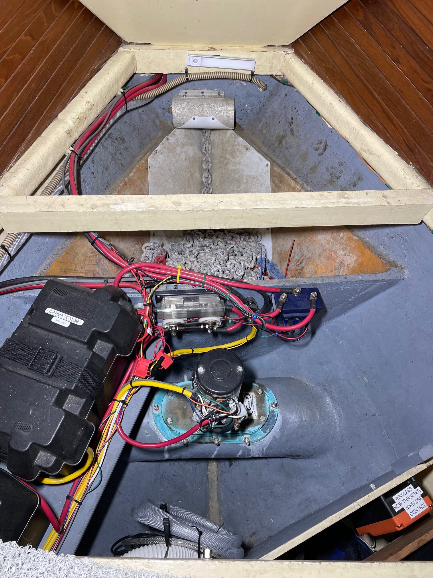
To access the lower locker, the front third of the v-berth mattress is folded back to expose a removable panel. The reason a person is required to stack the chain is because the lower section of the chain locker was partitioned off to make room for a bow thruster, batteries, and associated fuses and windlass controls. With a smaller, shallower chain locker, when all 300′ of chain is in, the top of the pile is higher than the point where the chain exits the hawse pipe so a person is needed to “stack the chain” as it’s being brought in.
Shows How The Bow Thruster & Batteries Take Up Part Of The Chain Locker
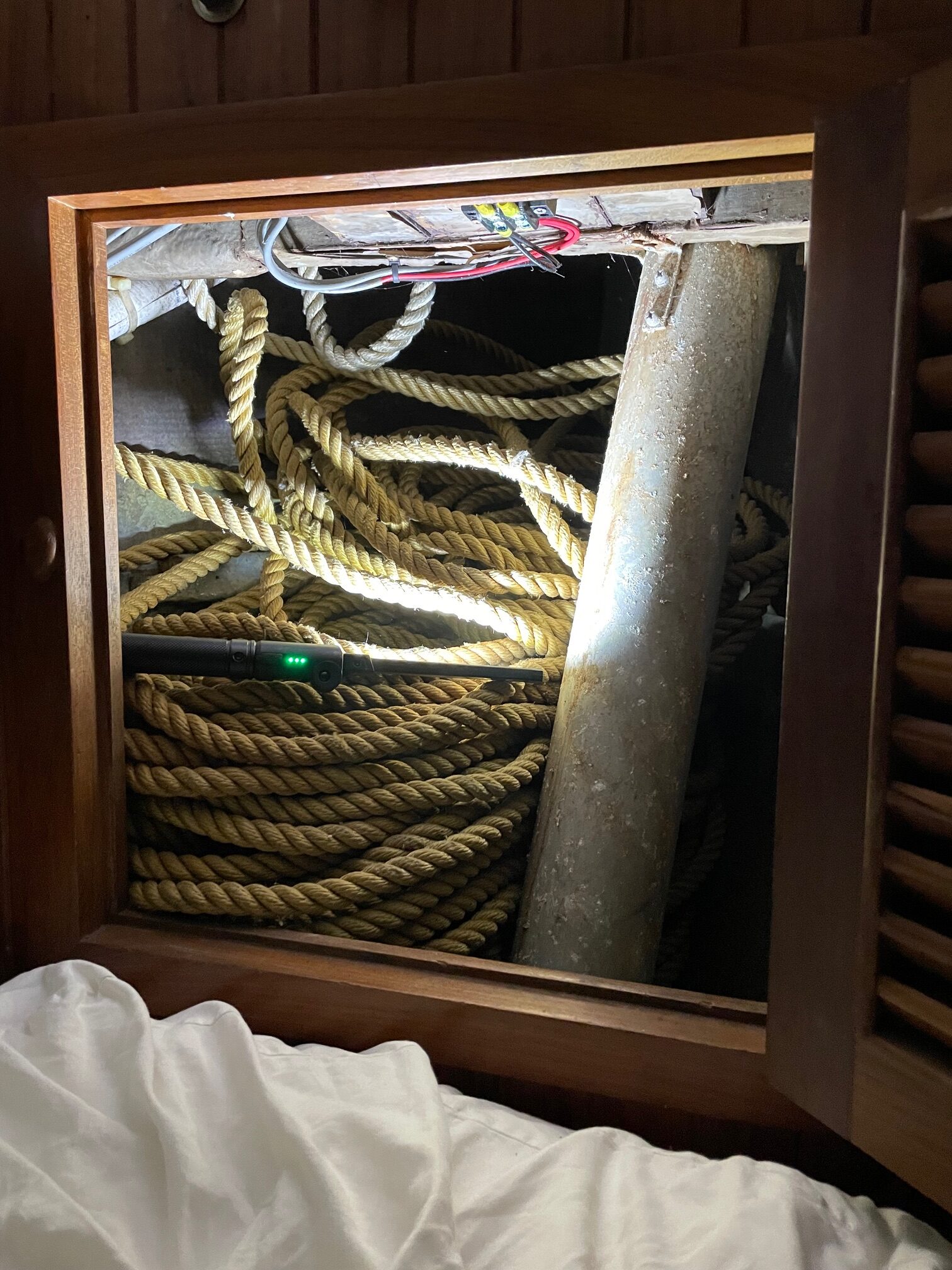
In regards to the upper locker where the 3-strand rope is stored, it also has it’s own problems–coiling 300′ of 3-strand rope takes up a lot of room and is messy. Taking the rope out while dropping the anchor and then re-coiling it when bringing the anchor up has to be done slowly and requires a person below. But this secondary anchor is seldom used and is mostly a back-up to the primary anchor (the exception is anchoring in gale conditions where it may be necessary to put out both anchors). We have only used this anchor twice in 20 years and it was in calm conditions and shallow water just to try it out.
New Configuration
I was aboard another Hans Christian 43 in the Puget Sound region with a different interior layout. It had a head up front where my V-berth bunk is, and a Pullman berth where my port side head is. The Pullman vs V-berth configurations were choices given to new owners during the build process. In the Pullman configuration, the chain locker is forward of the head and is accessed through a small door, exactly like the upper (secondary) locker is on Apropos. In the Pullman configuration, the lower locker that’s on Apropos is used for plumbing and the holding tank.
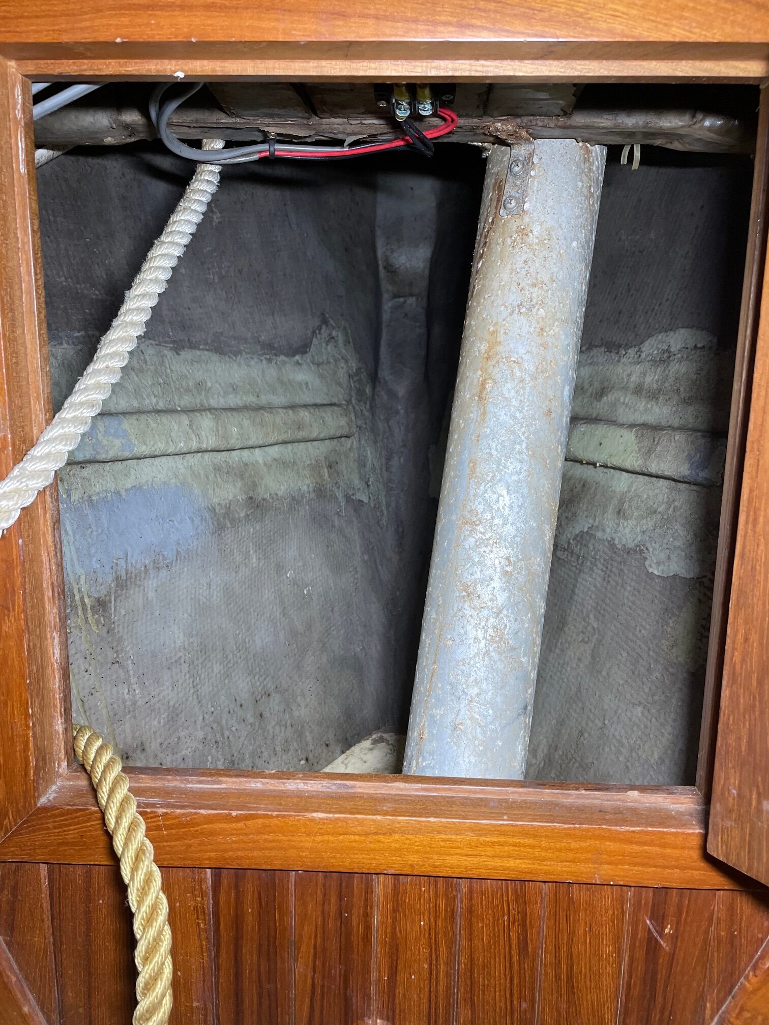
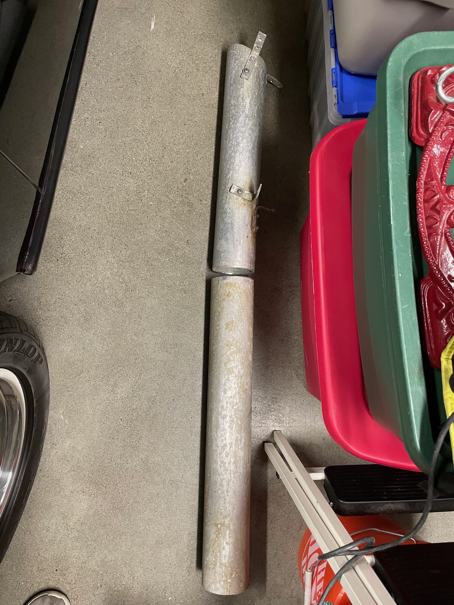
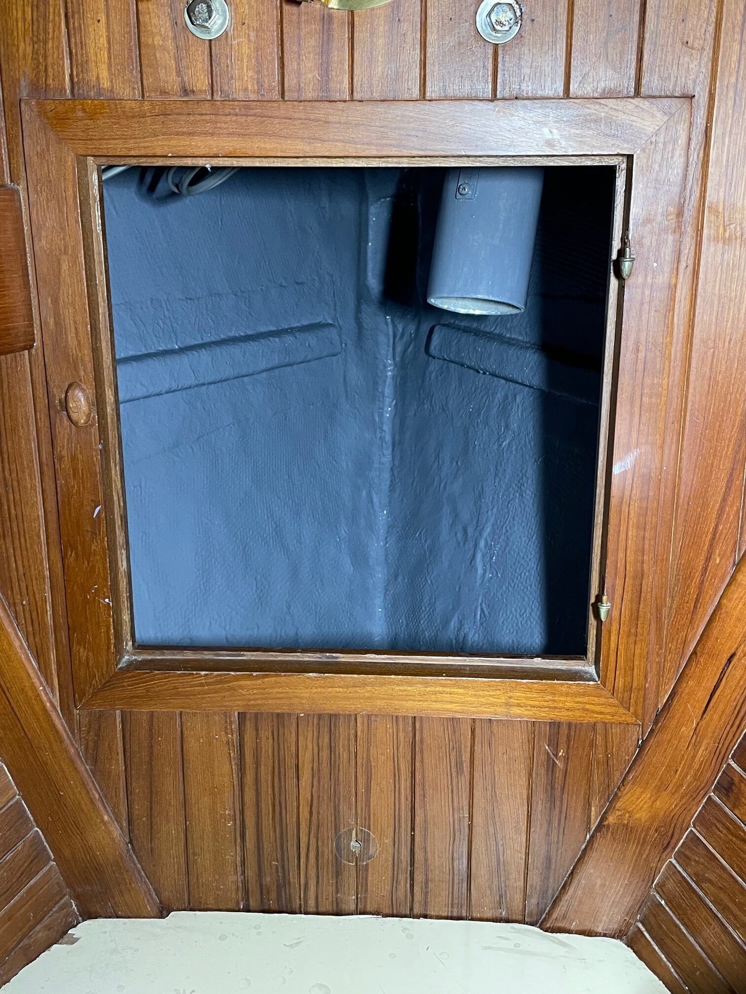
So it occurred to me, why not use the upper locker to store the primary anchor chain (either 300′ or part of it)? To do this, I first removed and cut the hawse pipe that runs through the locker. While I had it out, I cleaned and painted the locker and also the pipe (I plan to make a collar to be able to re-join the pipe in case I want to restore it back to original).
Upper Locker with Hawse PipeCut Hawse PipeUpper Locker after Painting and Re-installing Cut Hawse Pipe
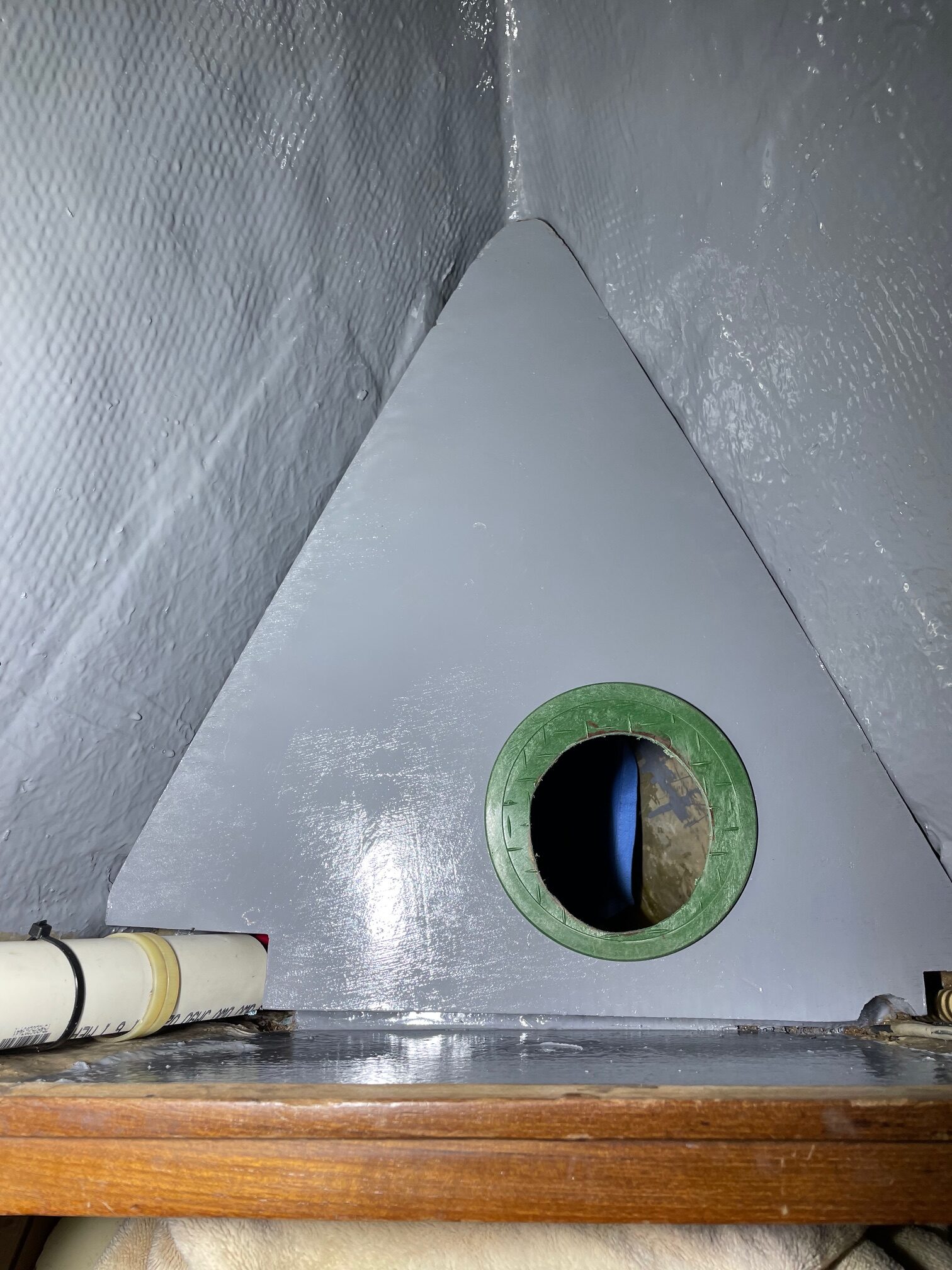
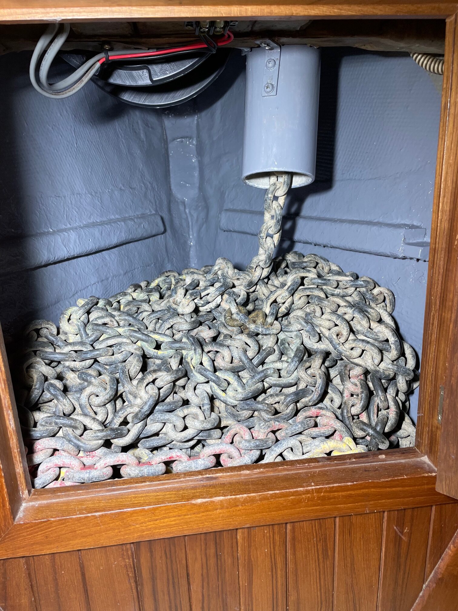
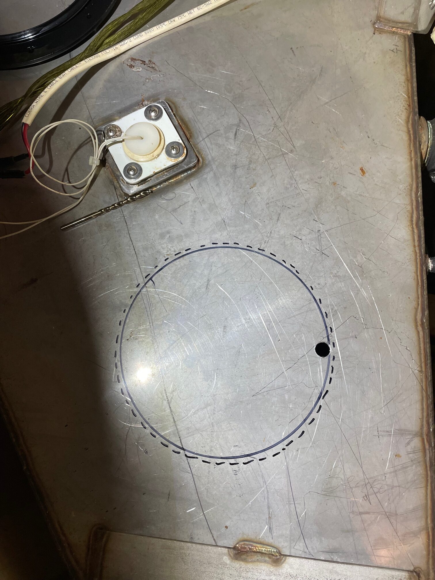
I also decided to store part of the chain in the lower locker to decrease the chain pile in the upper locker. After experimenting, I came up with 225′ in the upper locker and 75′ in the lower. The floor of the upper locker looks like this with the hole leading to the lower locker. Here’s a picture showing 225′ of chain stacked in the upper locker.
Upper Locker Floor225′ Chain
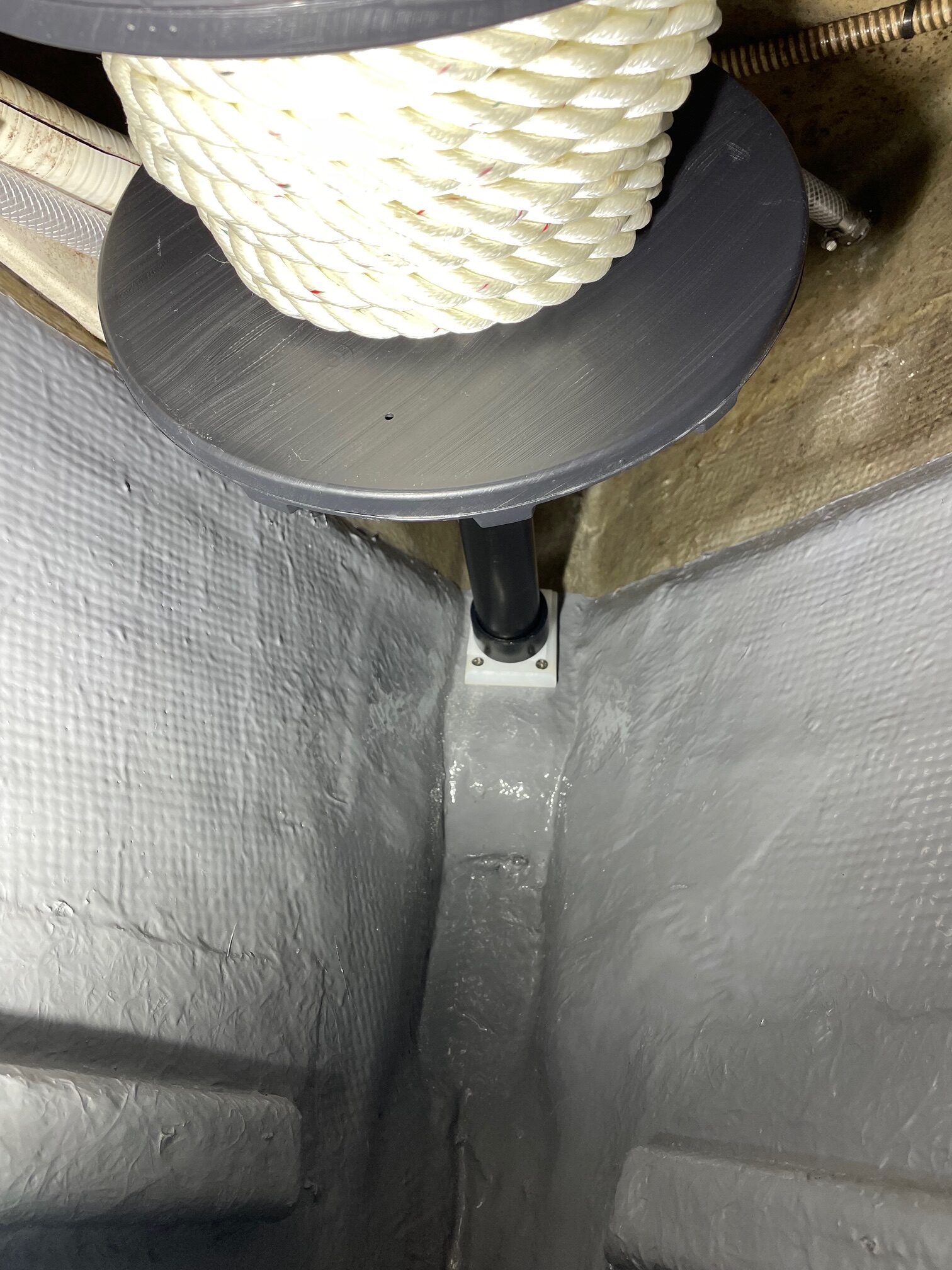
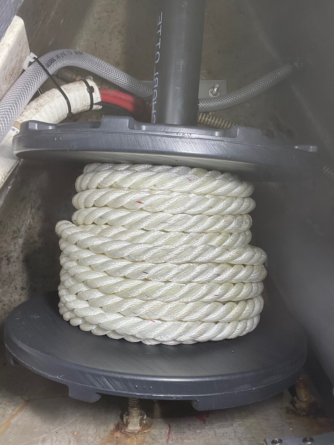
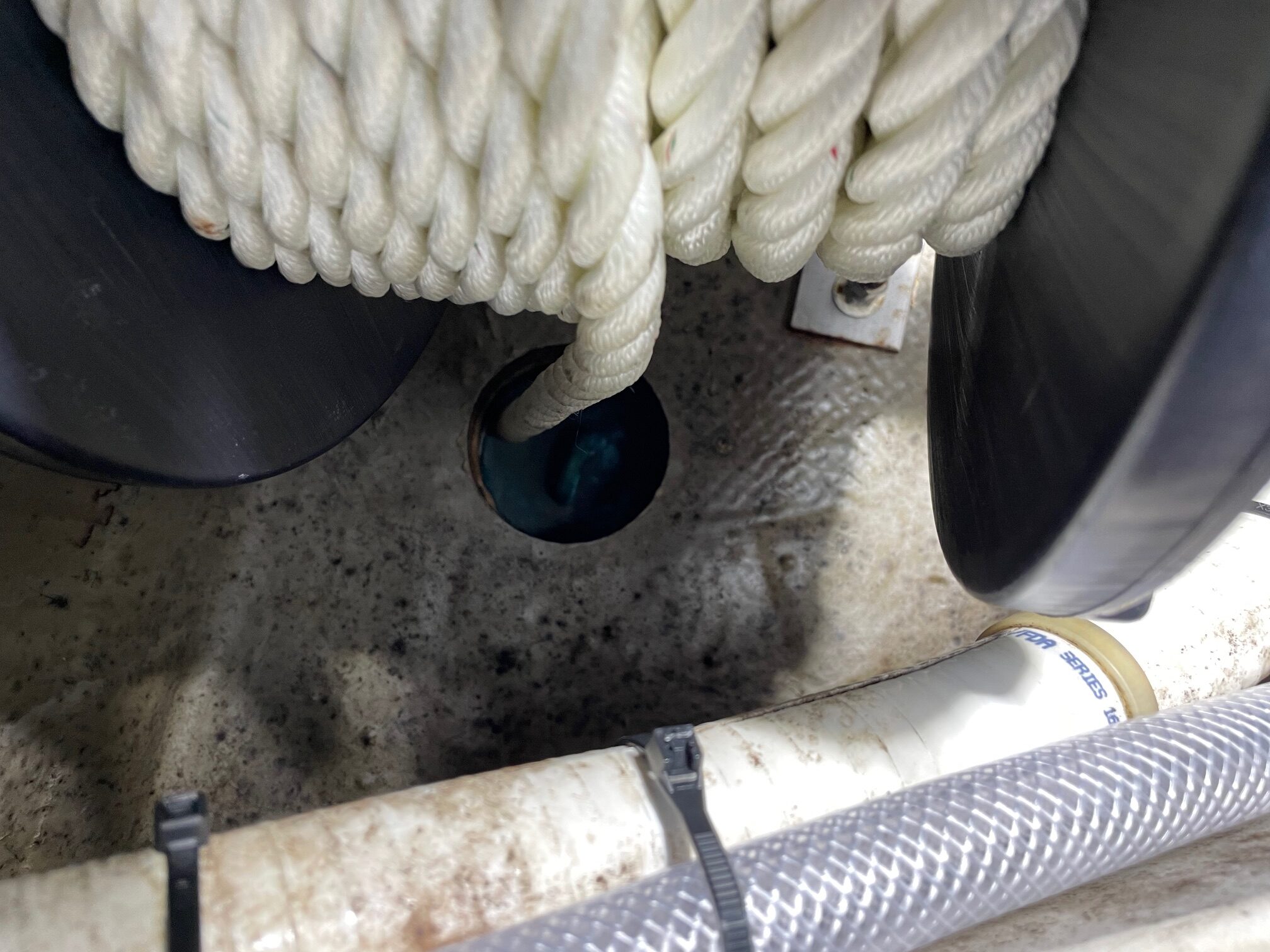
Since the upper locker is where the secondary anchor 3-strand rope used to be stored, I thought about how I could still have some line in the locker to be used for the secondary anchor. I came up with the idea of installing a spool with enough rope to be useful for a lunch anchor, where you just want to drop an anchor for a short stopover. This is usually done in shallow waters and calm conditions when putting the larger anchor with chain isn’t required. I mounted a black ABS pipe running fore/aft in the upper part of the locker. The pipe serves as an axle for the spool and is held on each end with endcaps that are mounted to starboard, then the starboard is mounted to bulkheads. I had to custom make wedges because the surfaces where the endcaps were mounted were not perpendicular to the pipe. The spool is big enough to hold 150′ of 1/2″ 3-strand nylon rope. The deck hole where the rope goes to the windlass is directly above the spool. I also saved the original 300′ of 3-strand and put it on a larger spool to keep on the boat for emergency use (in gale conditions or if I ever lose the main anchor).
Secondary Anchor 1/2″ Rope on SpoolSpool and ABS Pipe for AxleExit Hole Directly above Spool
For now, I put 60′ of 1/2″ 3-strand nylon rope on the spool, after testing it out in the spring, I’ll replace it with the maximum amount of rope that fits on the spool, about 150′.
These modifications should make anchoring a lot easier. I’m looking forward to trying it out in the spring.
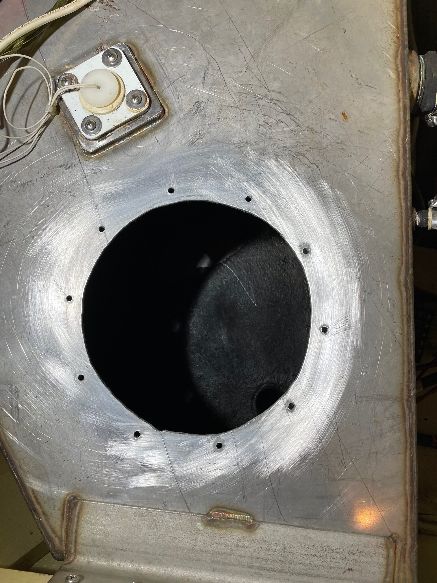
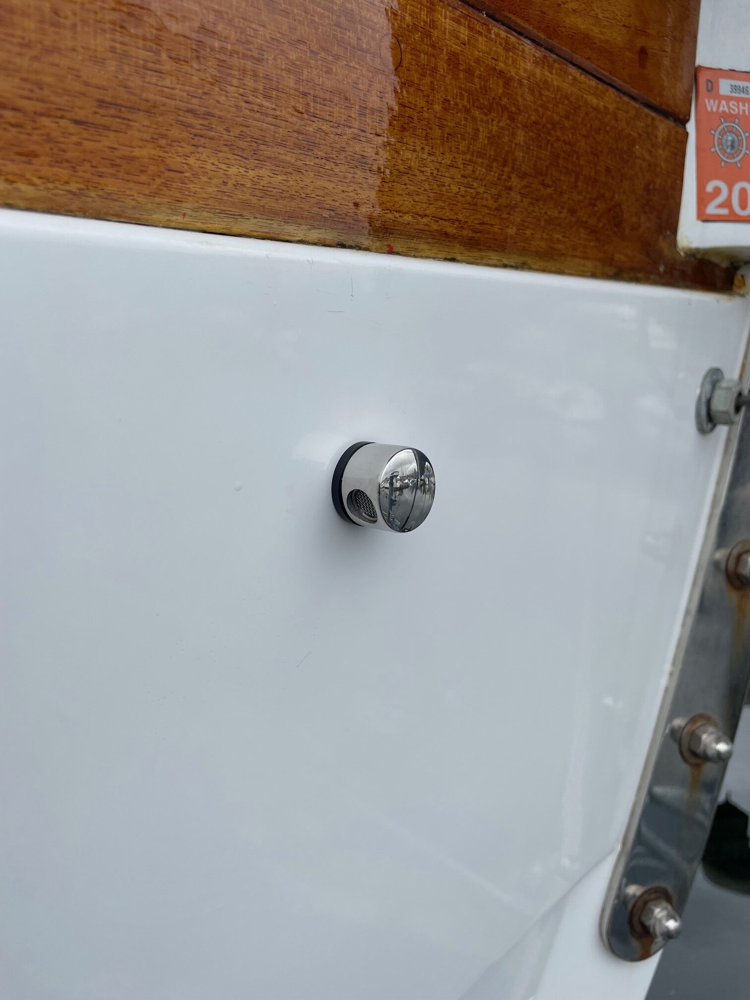
Apropos has a 20 gallon stainless steel holding tank (black water tank). An electric toilet flushes into it, and a drain at the bottom leads to a macerator pump for emptying it. A port at the top side is for a vent. Ventilation is very important for holding tanks and is needed for turning anaerobic bacteria (smelly) into aerobic bacteria (not smelly). A 3/8″ hose connects to the existing vent port and runs about 20 feet to a thru hull fitting at the bow (port side). This location was chosen to be at the highest part of the hull to keep sea water from going in. The problem was that the vent size was too small, which limits the amount of air reaching the tank.
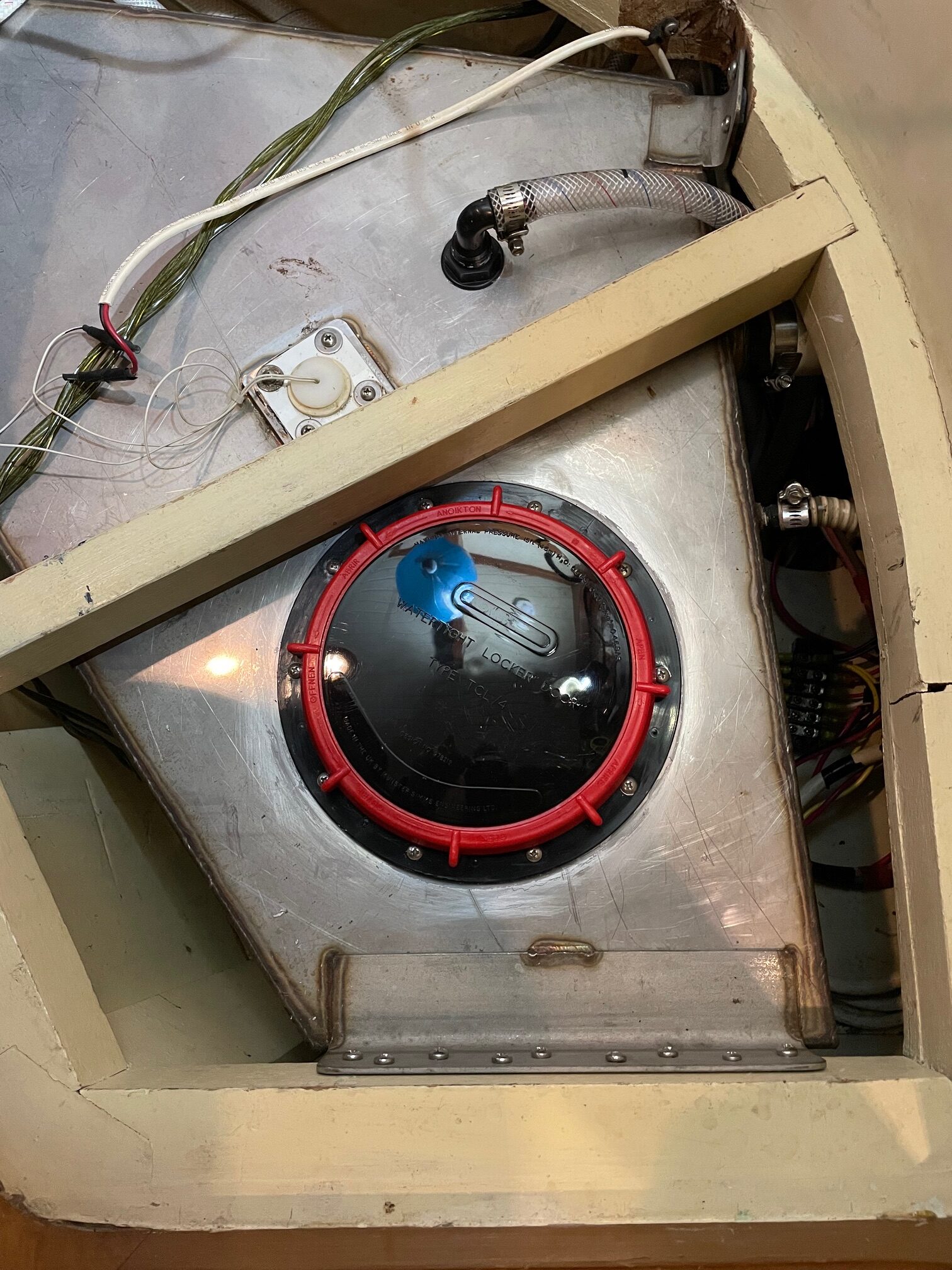
The improvement involved adding another vent with a larger port and a larger hose. This should more than double the amount of oxygen reaching the holding tank. An additional task was to add an 8″ port to the top of the tank, useful for inspections and cleaning. I also removed the tank monitor that’s mounted on the top of the tank and gave it a good cleaning.
I used a hole saw to make the hole for the vent, and a jigsaw to cut the hole for the inspection port. Drilling and cutting into stainless steel requires special carbide tipped drill bits and jigsaw blades and a lot of patience (it took over an hour to cut the hole for the 8″ port). I ran the 5/8″ vent hose to the same location as the original vent, except I put the thru hull fitting on the starboard side so now the tank is vented to both sides of the boat.
Holding Tank Inspection Port Cut PatternCut and Drilled for MountingNew Inspection Port and Air VentFitting for Air Vent
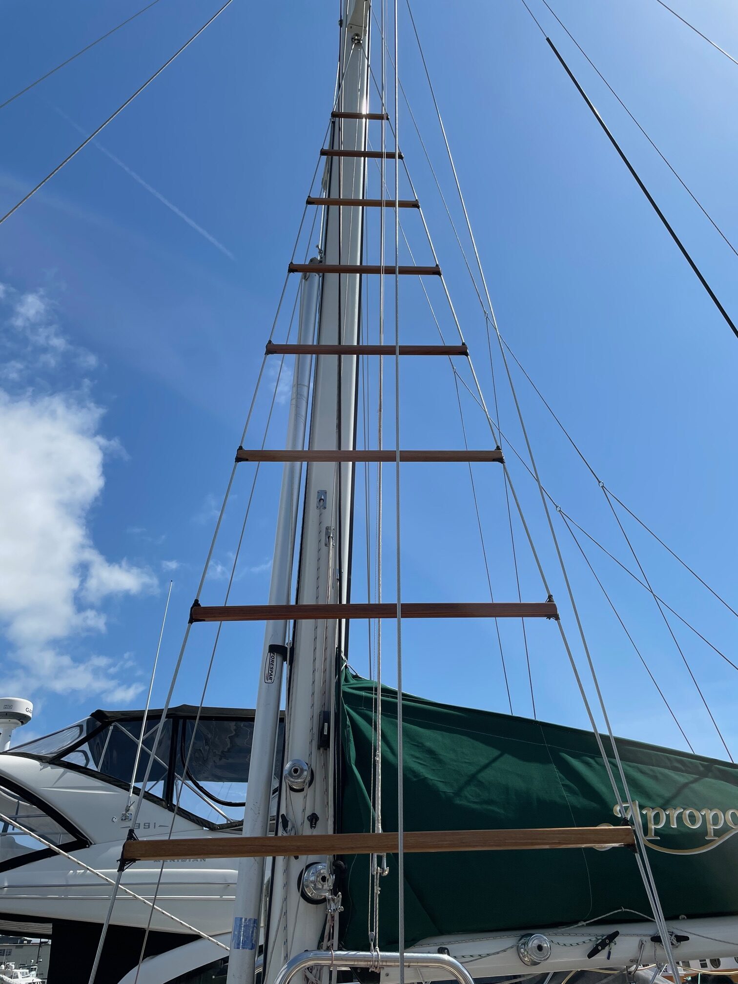
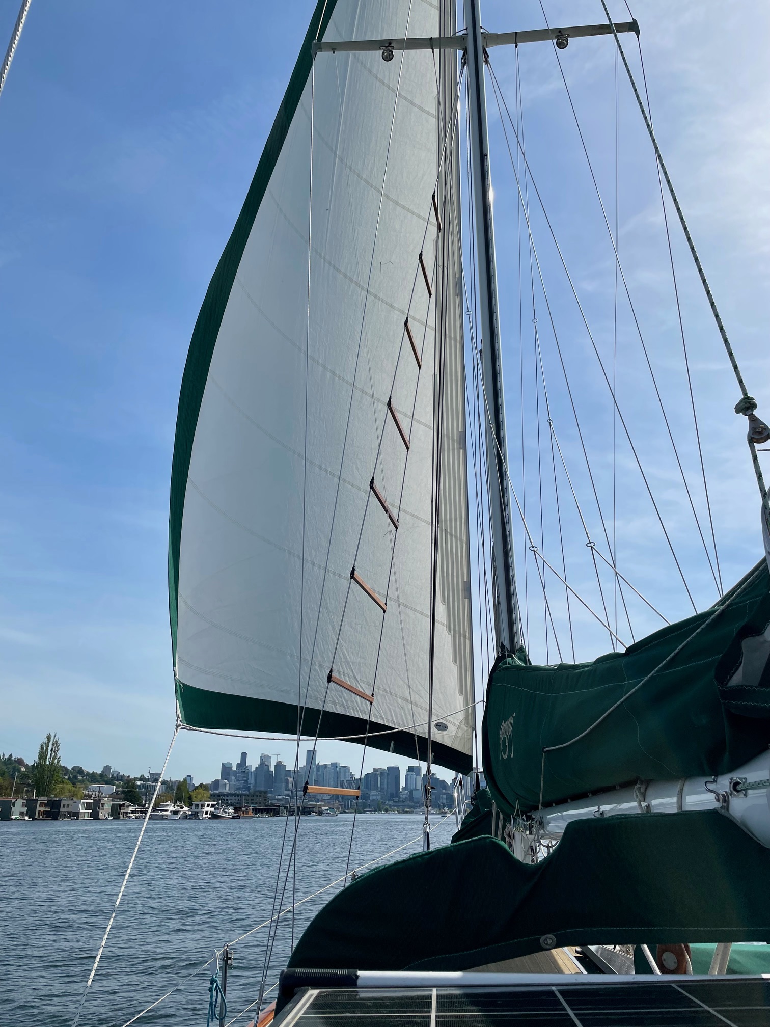
Back in 2014, before leaving on our South Pacific trip, I made ratlines for the port side shrouds on the main mast. They were useful in spotting reefs and bommies in the clear waters near islands and atolls–being higher up in the rigging reduces the glare, making it easier to spot them. These ratlines were made up of 5 teak “ratboards” and 6 3-stranded rope “ratlines”.
2014 Version
The teak boards stayed in place for 10 years without moving, but I couldn’t get the lashing on the rope ratlines to hold them in place so they would sometimes slide an inch or two. While still functional, this made them appear uneven and looked bad until I slid them back in place. The other downfall of using the rope was it hurt when climbing barefoot whereas the teak boards were way more comfortable on bare feet.
Since I had to remove the ratlines when replacing the standing rigging in 2024, it gave me a chance to redo and improve them. I decided to do away with the 3-strand rope steps and use all teak ratboards. I already had the extra teak left over from 2014, so it was just a matter of deciding on the number of steps and spacing. I ended up using the original 5 teak boards and making an additional 3 more for a total of 8 ratboards, spaced about 28″ apart.
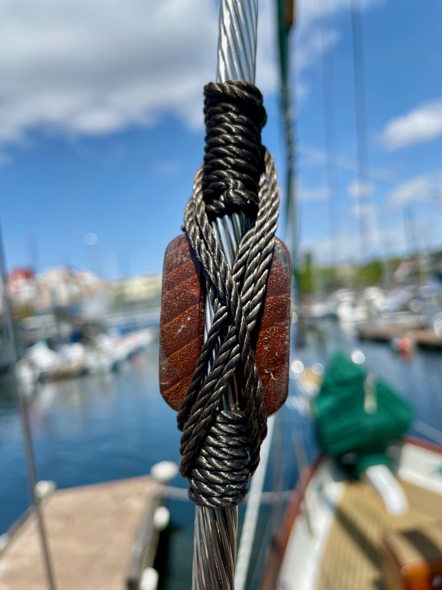
Lashing
I used a slightly different lashing method that looks cleaner and should keep the ratboards in place for many years. Before installing them, I sanded each board and applied 5 coats of teak oil. An annual coat of teak oil should keep them looking good.
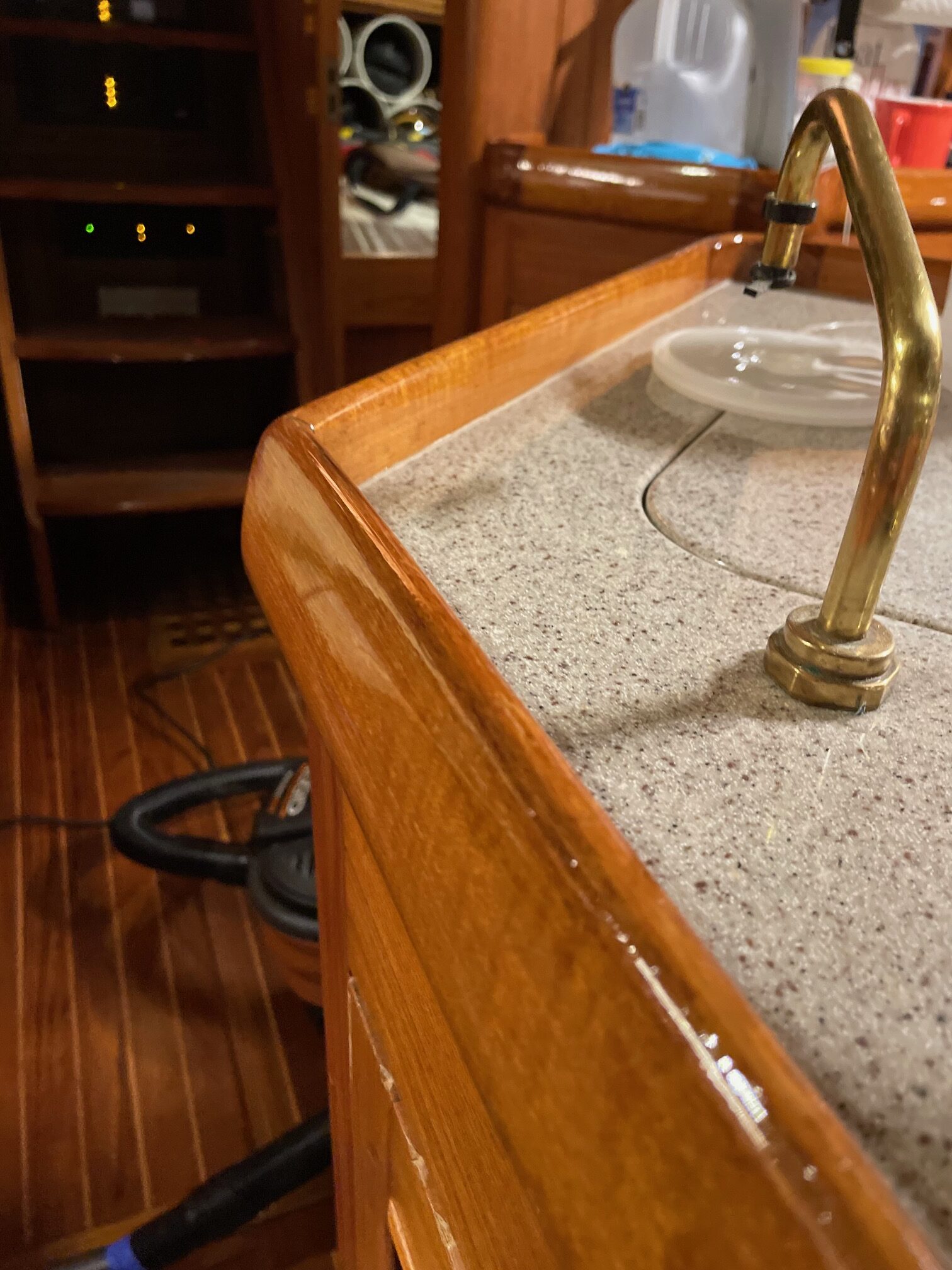
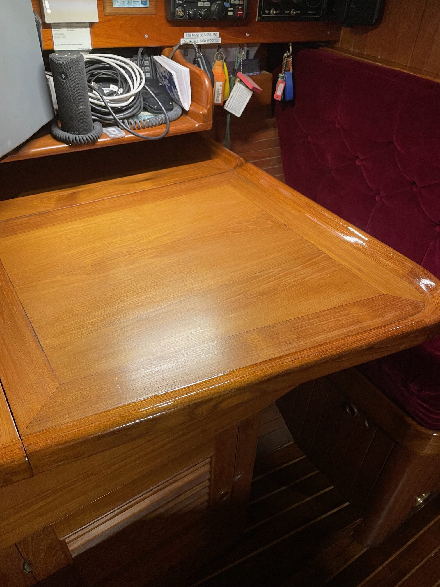
Having just finished the big project of re-finishing the cabin sole, I decided to continue with some additional interior varnish work. The teak interior is finished in mostly satin varnish, but certain trim parts are done in gloss. As with the sole, I haven’t touched any of the interior varnish since buying the boat 20 years ago.
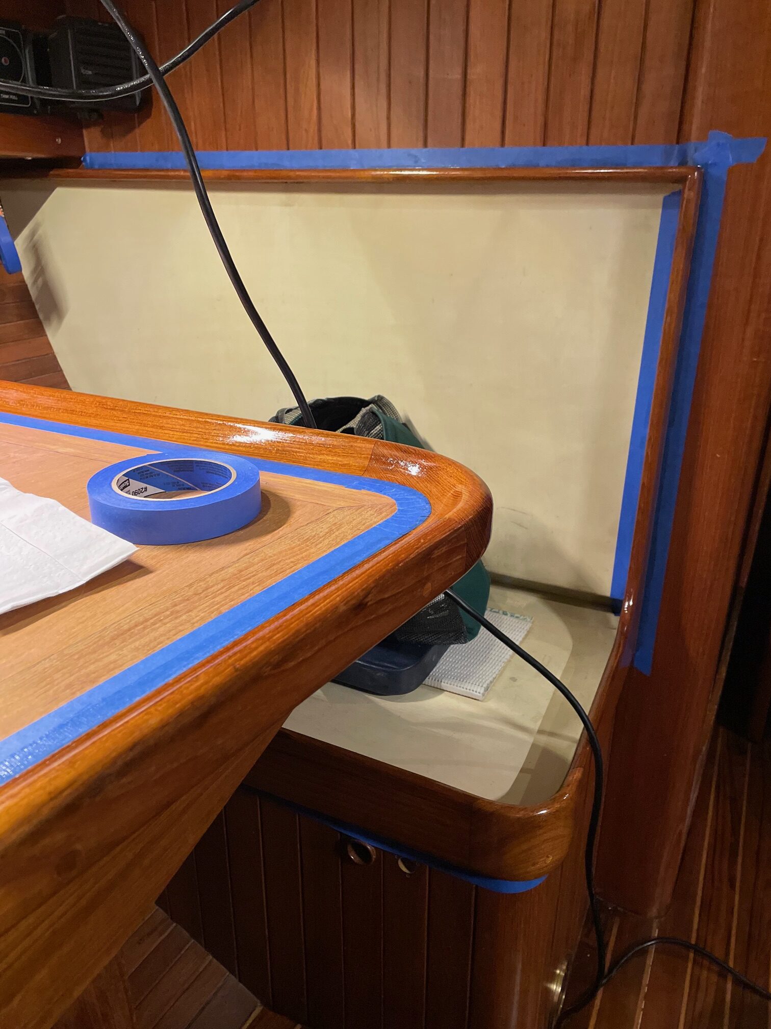
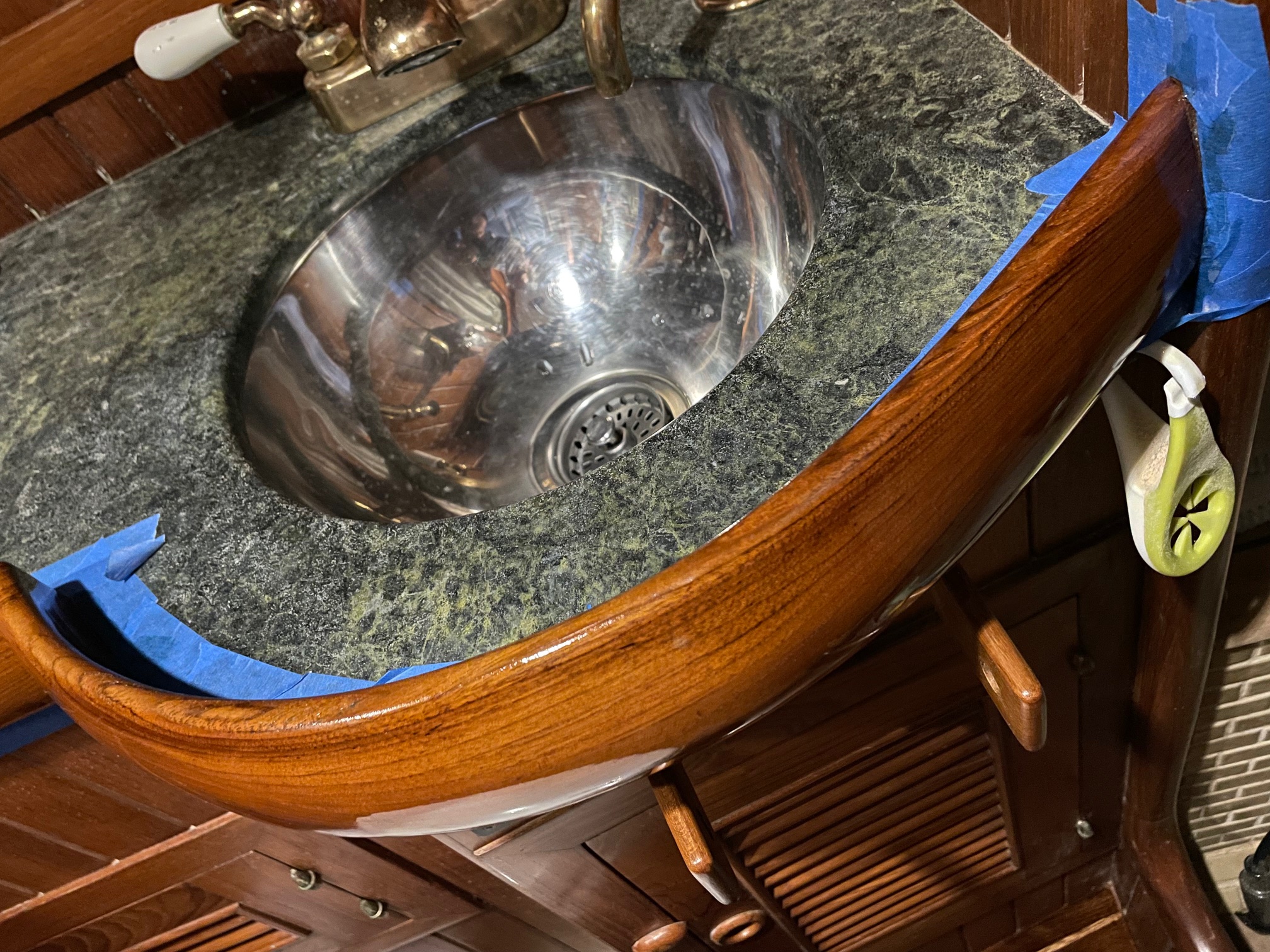
I began with the trim parts that were done in gloss. This included the trim around the galley, chart table, settee, salon table, head sink, and bunks. I hand sanded to remove most of the old varnish, especially for parts that were well worn like the top rounded edge of the trim. Most of the vertical trim parts only required a light sanding. I applied 3 coats of Pettit Flagship varnish, lightly sanding between each coat.
Galley TrimChart TableSalon TableHead Sink Trim
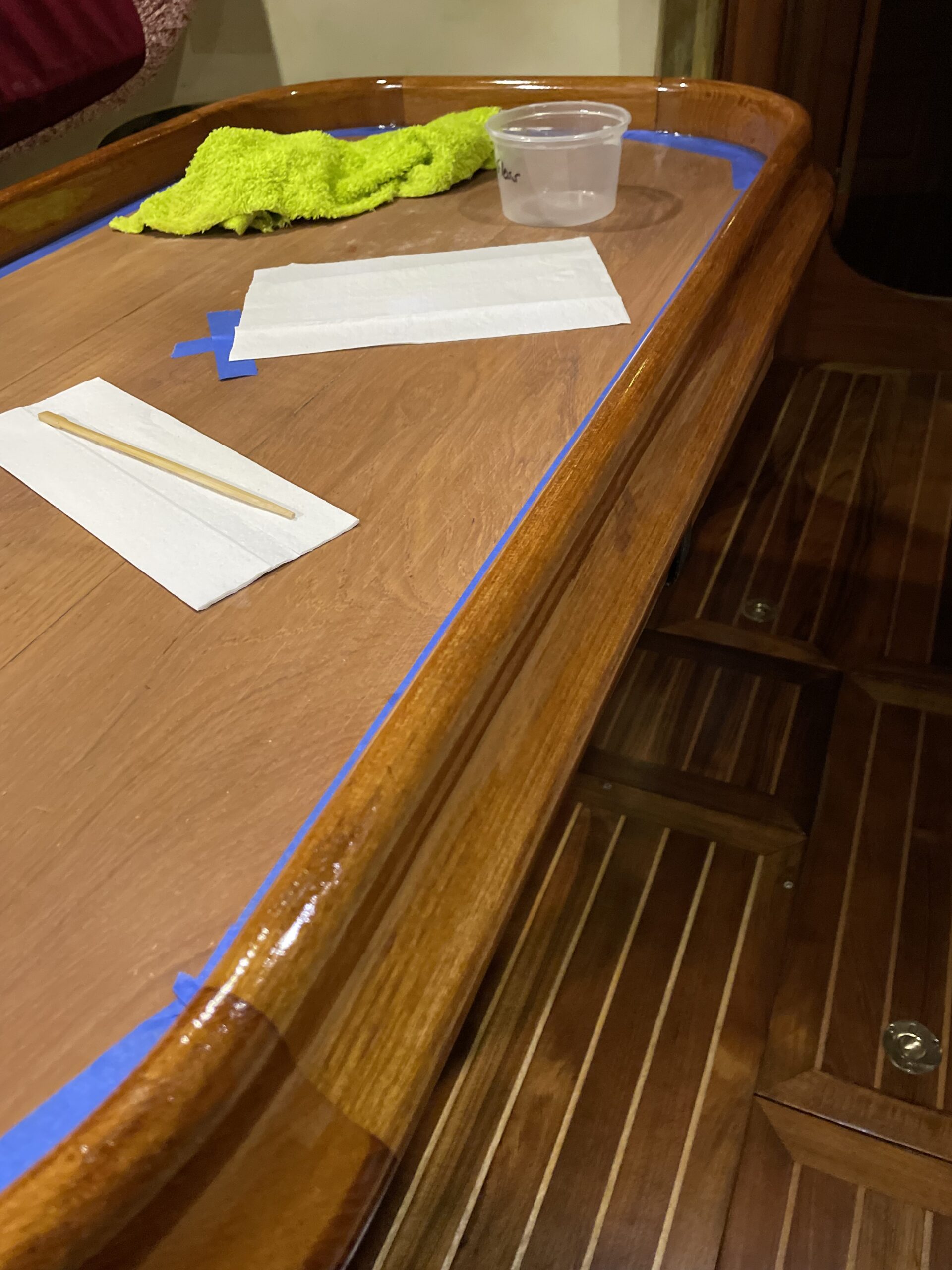
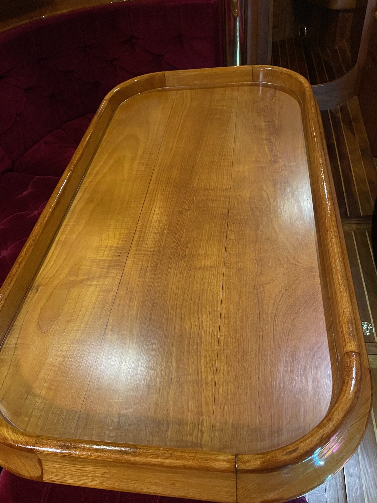
Next I re-finished the horizontal surfaces of the chart table, salon table, and settee table. After sanding with 80 grit to remove the old finish, then 240 grit, I applied 4 coats of Pettit Flagship Satin. The pictures below show the outer trim done in gloss and the horizontal surface in satin.
Chart TableSalon Table
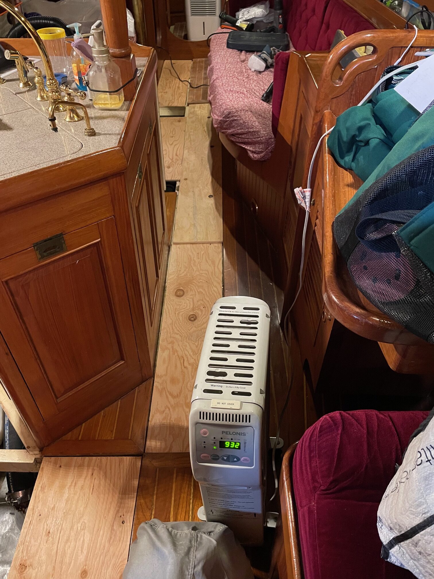
Refinishing the interior teak is a good winter time project. I ran a heater and dehumidifier to keep humidity at 60% and temperature around 60 degF for better drying and working conditions. I’ll take a break from it for now since sailing season is fast approaching.
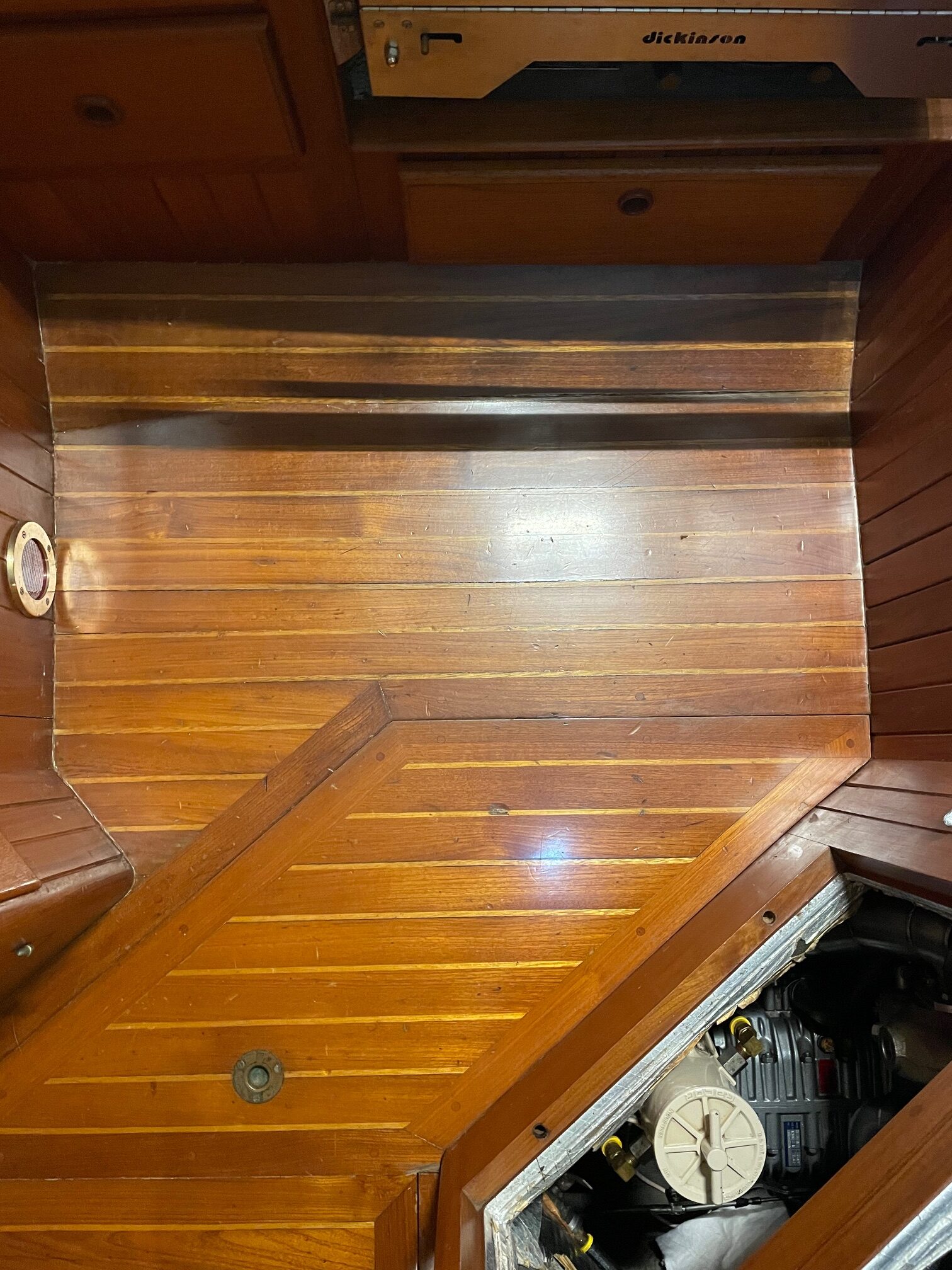
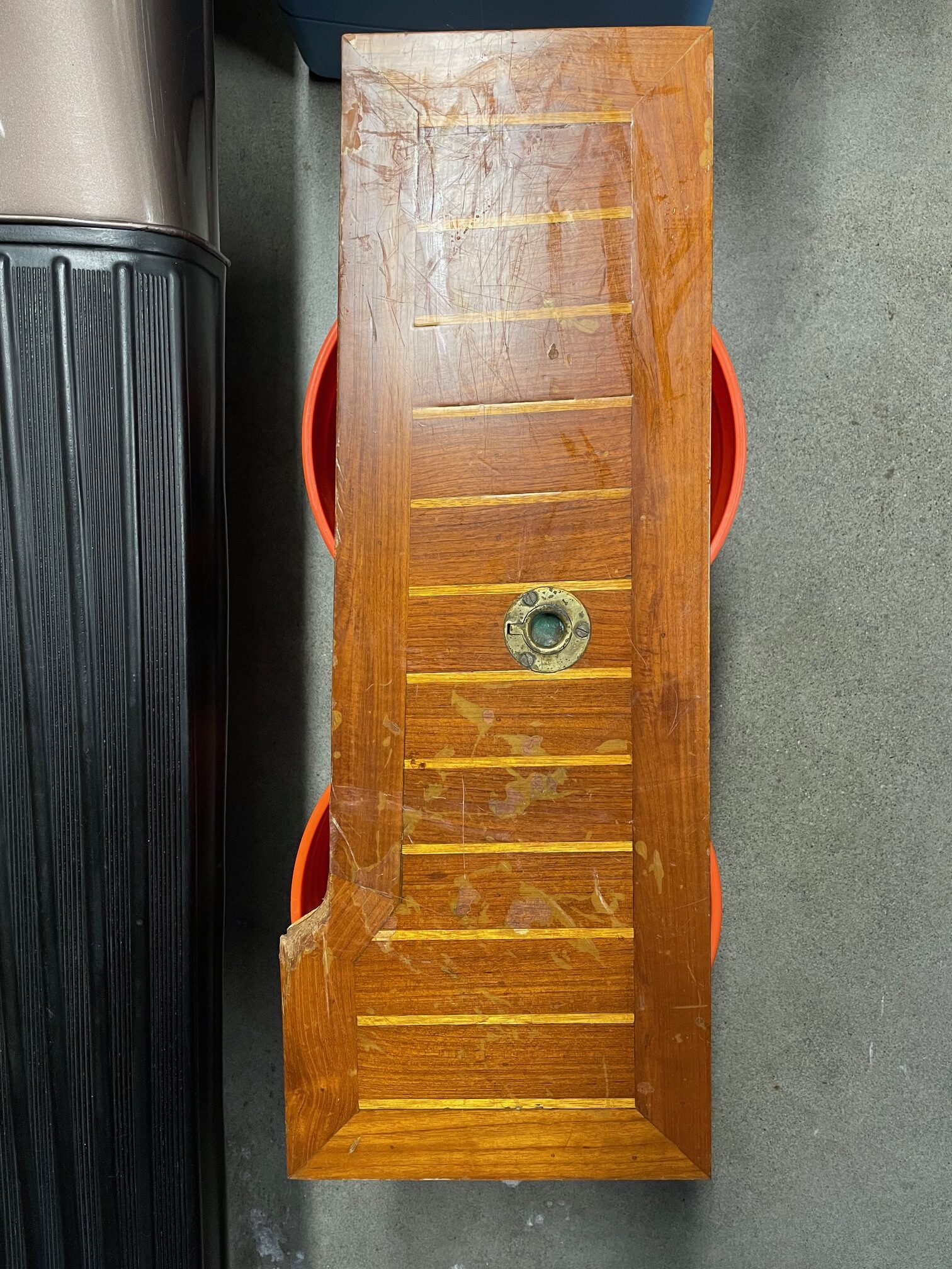
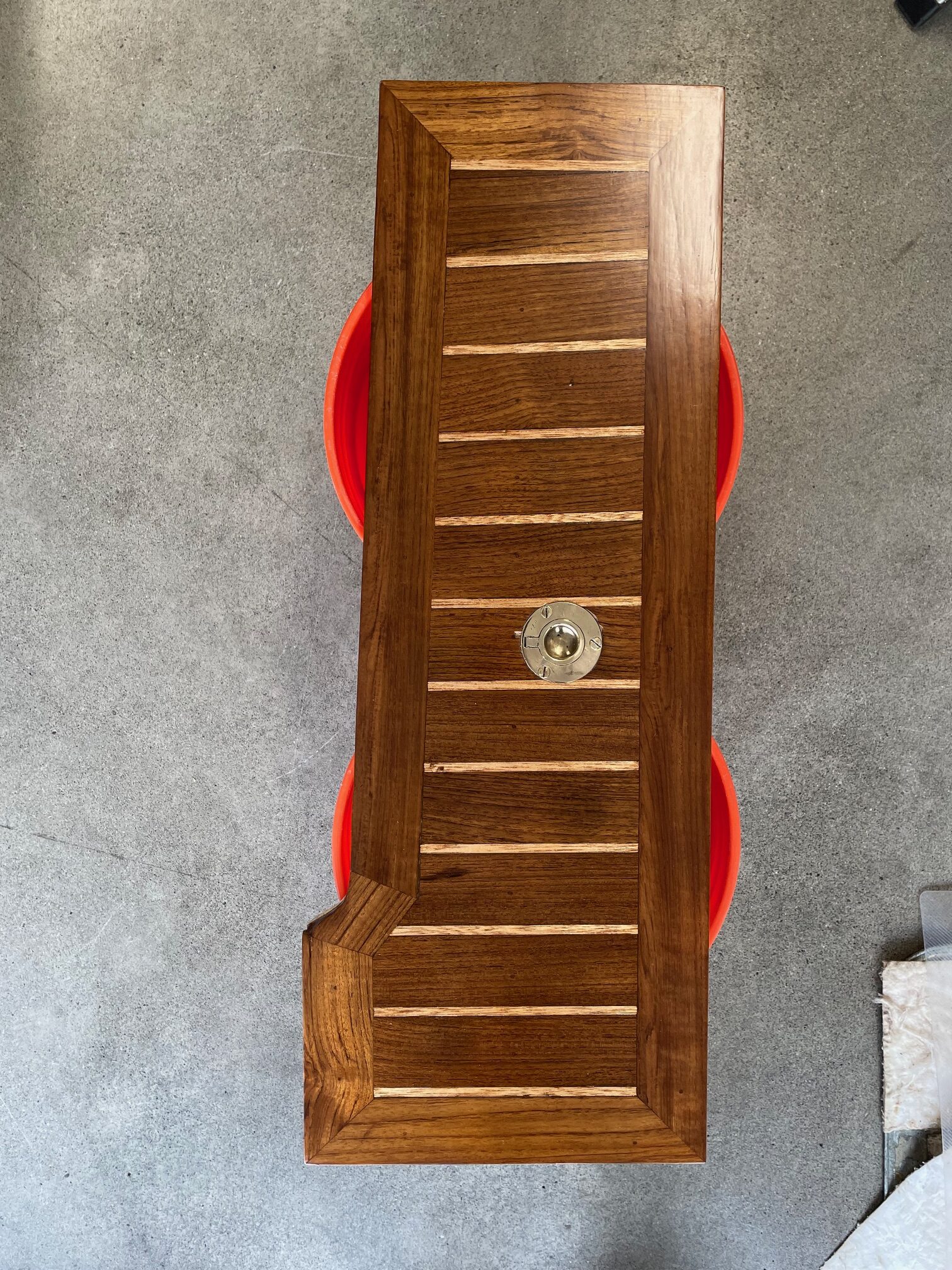
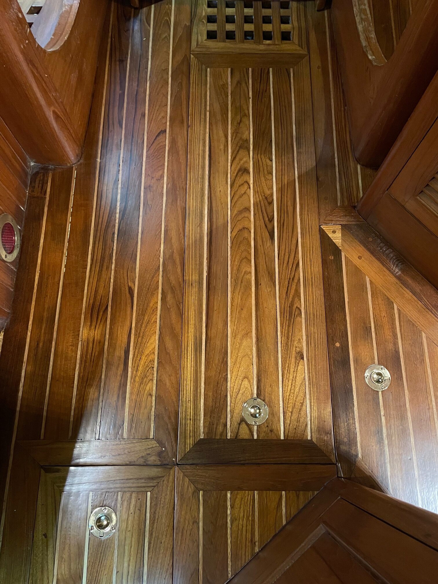
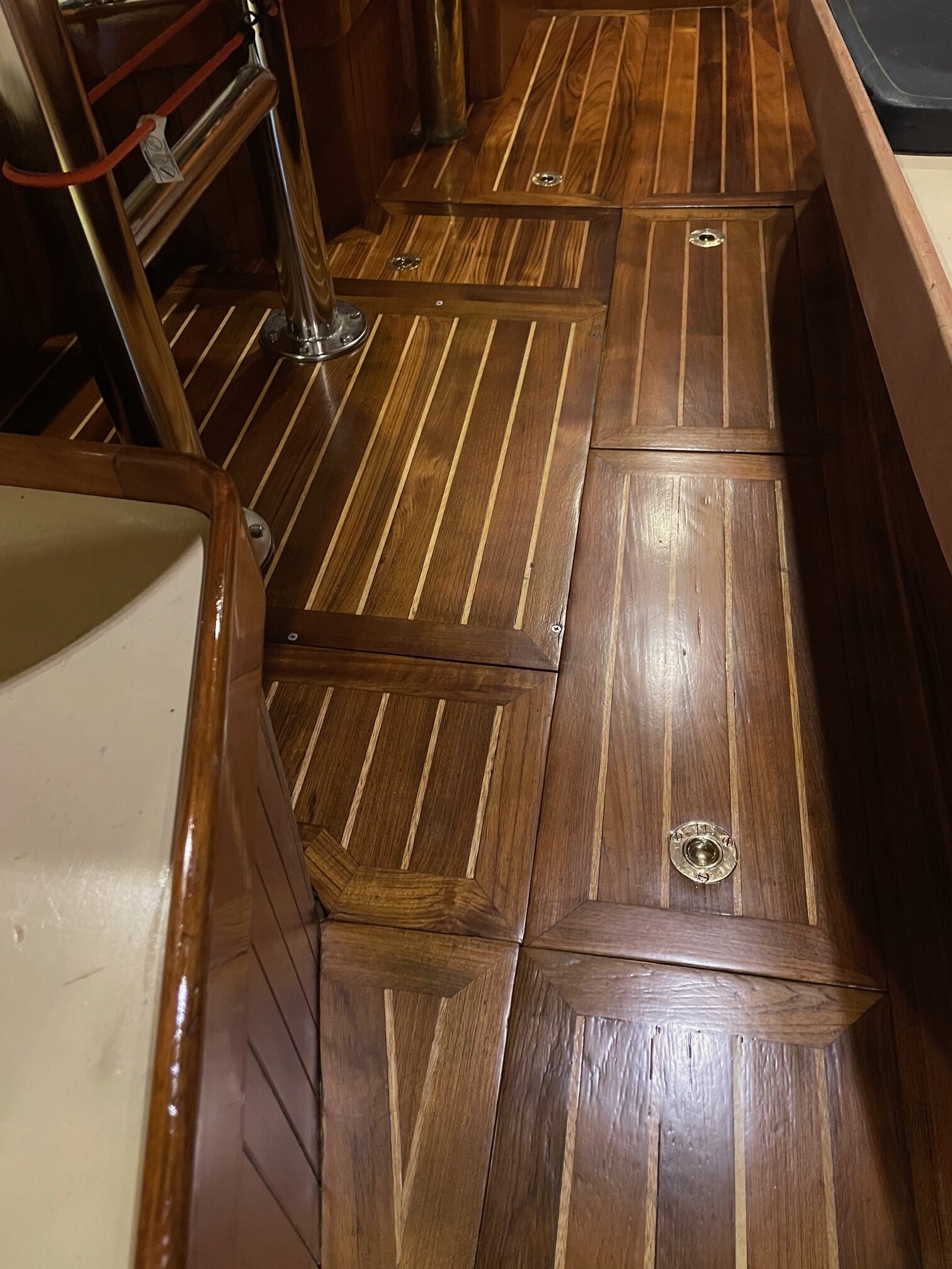
When we bought Apropos in 2005, the teak cabin sole was in good shape for a 22 year old boat. The boat was lightly used during those 22 years and actually sat unused for 10 of those years. But after owning the boat for 21 years and sailing an estimated 25,000 miles, the finishing on the cabin sole was worn, with plenty of scuffs and scratches and even some dents from things flying around the cabin. So I decided to refinish the entire cabin sole. Shown below are a few pictures taken before I began–on the left is the galley floor and on the right is a panel that lies next to the part of the setee that is movable for accessing the front side of the engine. That section slides along the top of this panel, and has damaged the finish.
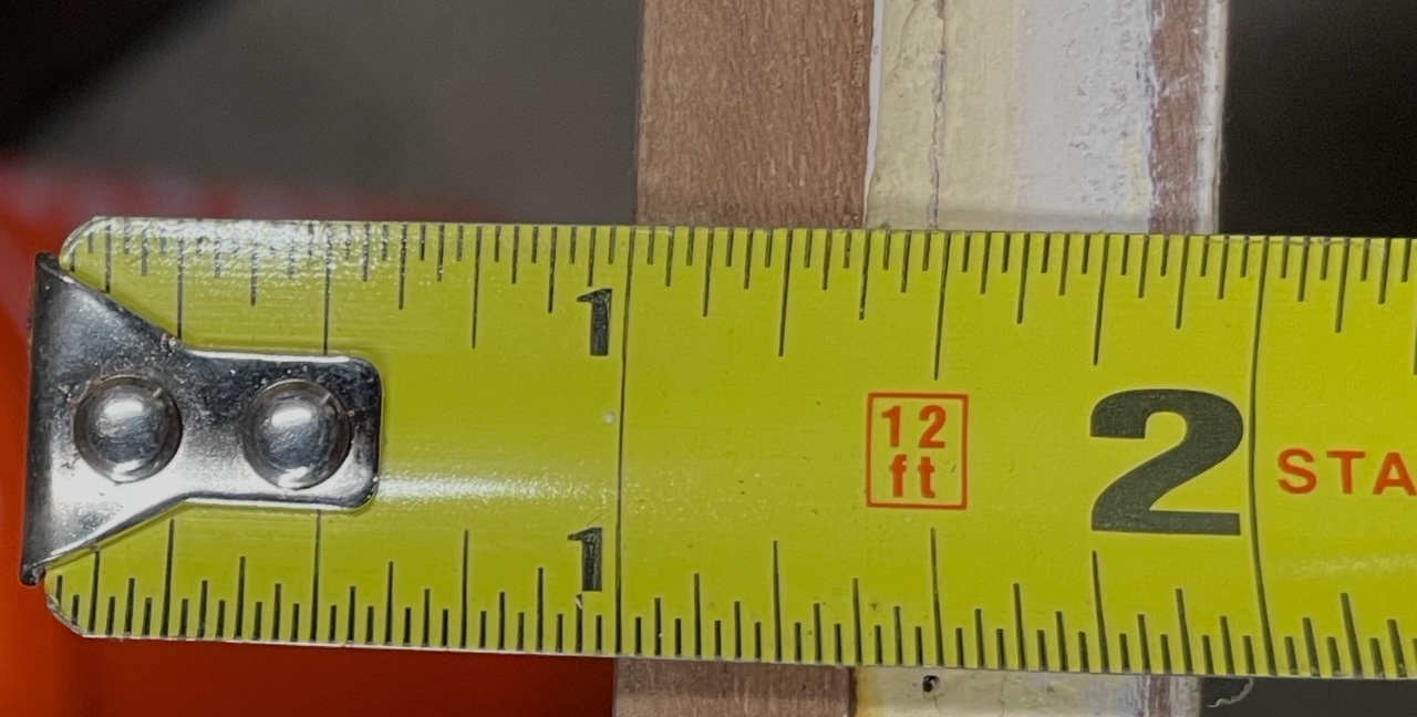
The sole is made of 2″ wide solid teak planks with 1/4″ strips of holly. Both teak and holly are rot-resistant hardwoods. The combination is a traditional look that provides a nice contrast between the dark teak and light holly. The solid teak and holly are 3/8″ thick, and glued to 9/16″ thick marine hardwood. Boats made in the 1970’s-1980’s used old growth teak which was plentiful 50 years ago. Today, most teak is plantation grown and what very few new boats that use teak, it’s typically only a thin veneer over plywood.
3/8″ Teak on left, 9/16″ hardwood on right
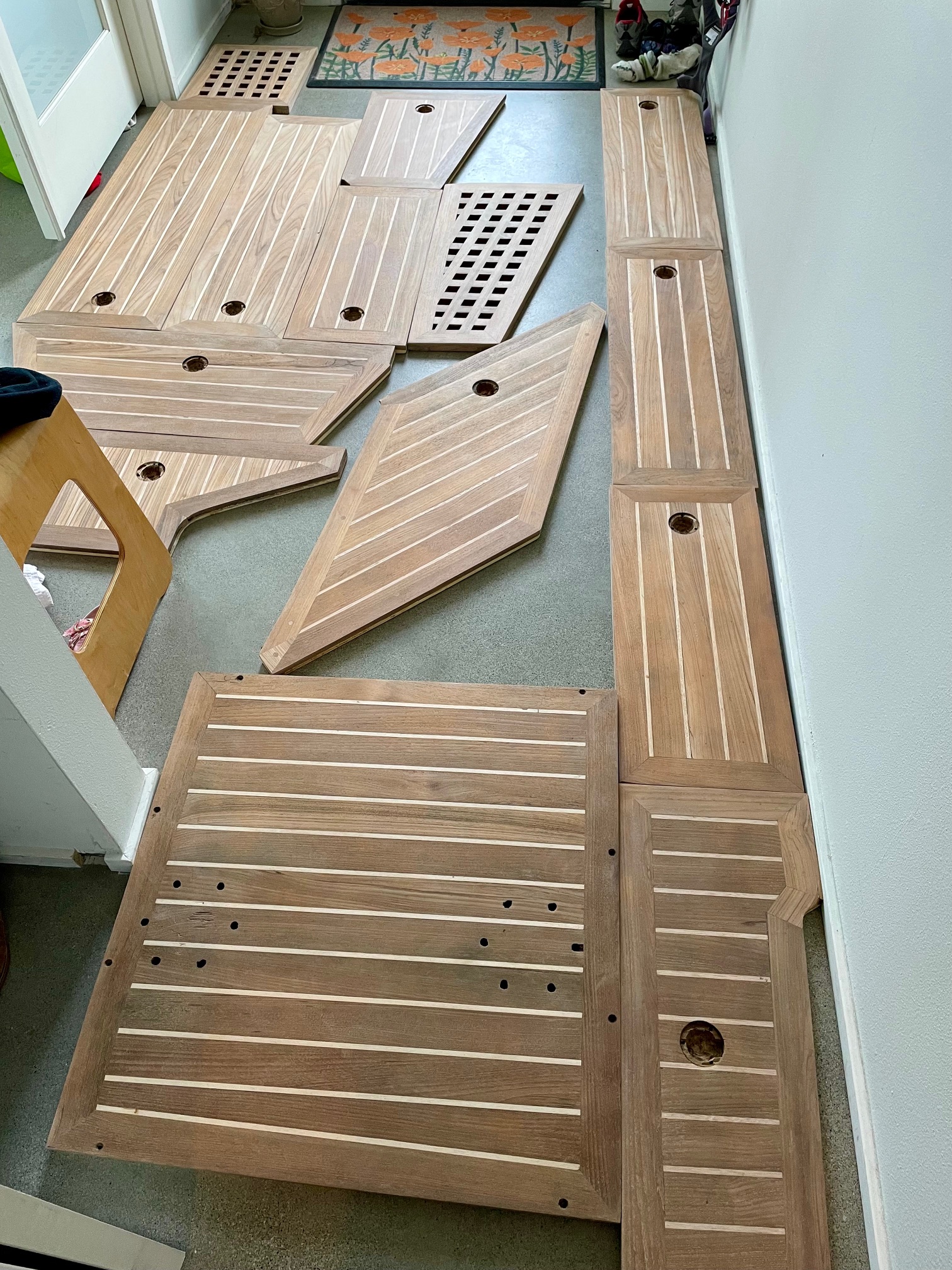
There are 14 removable panels, equaling about 2/3rd of the entire sole. These can all be removed and taken off the boat for ease of refinishing. The remaining non-removable teak will be refinished in-place on the boat.
I decided to use Awlwood products to refinish the sole. I’m very familiar with them from refinishing the entire exterior brightwork on Apropos. Instead of a yellow primer that I used on the exterior teak, I used a clear primer for the interior so the holly strips remain brighter for a better contrast with the darker teak. Then I applied 6 coats of clear gloss and a final 2 coats of clear matte.
Preparation
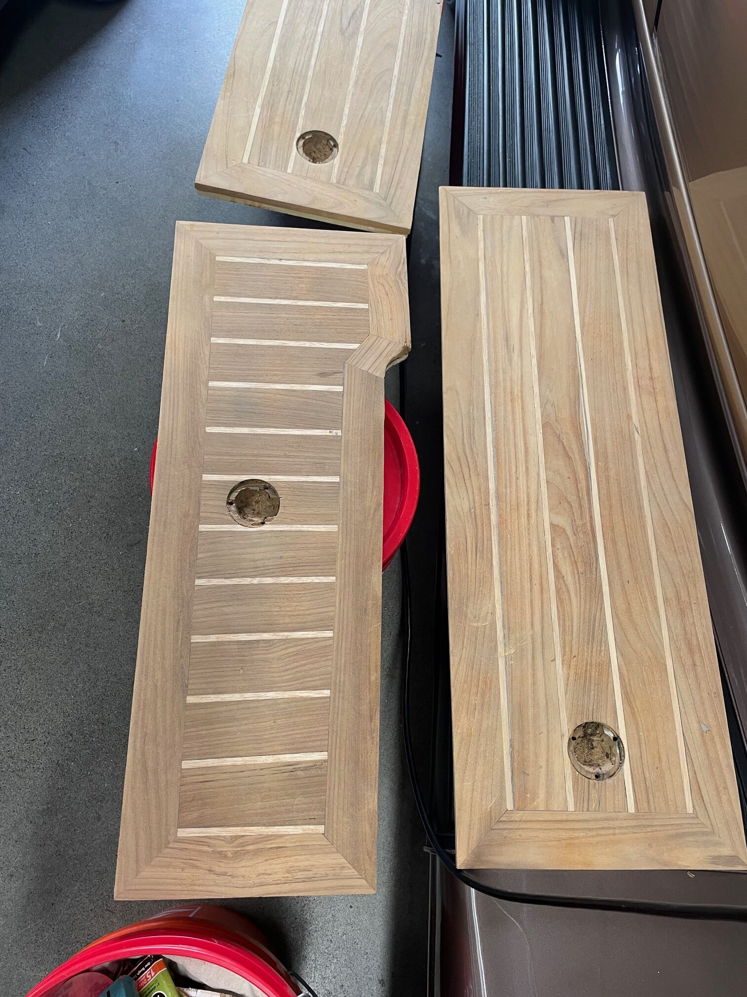
I took the removable panels off the boat to refinish. Here are the steps I followed:
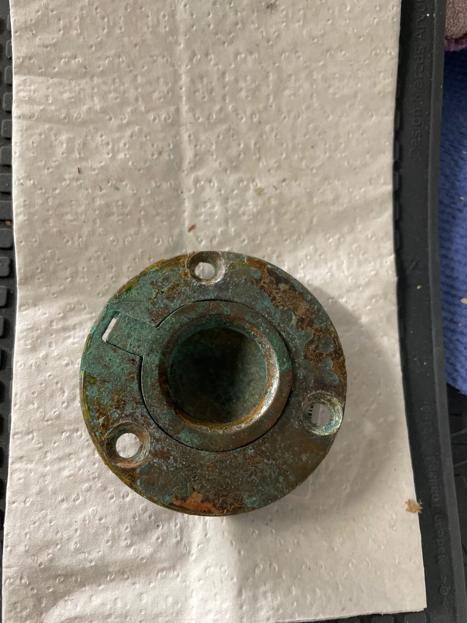
Remove brass hardware (pull rings)
Apply a chemical stripper and allow to sit overnight
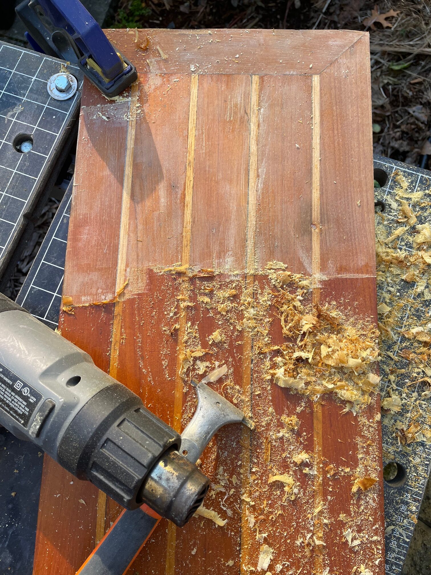
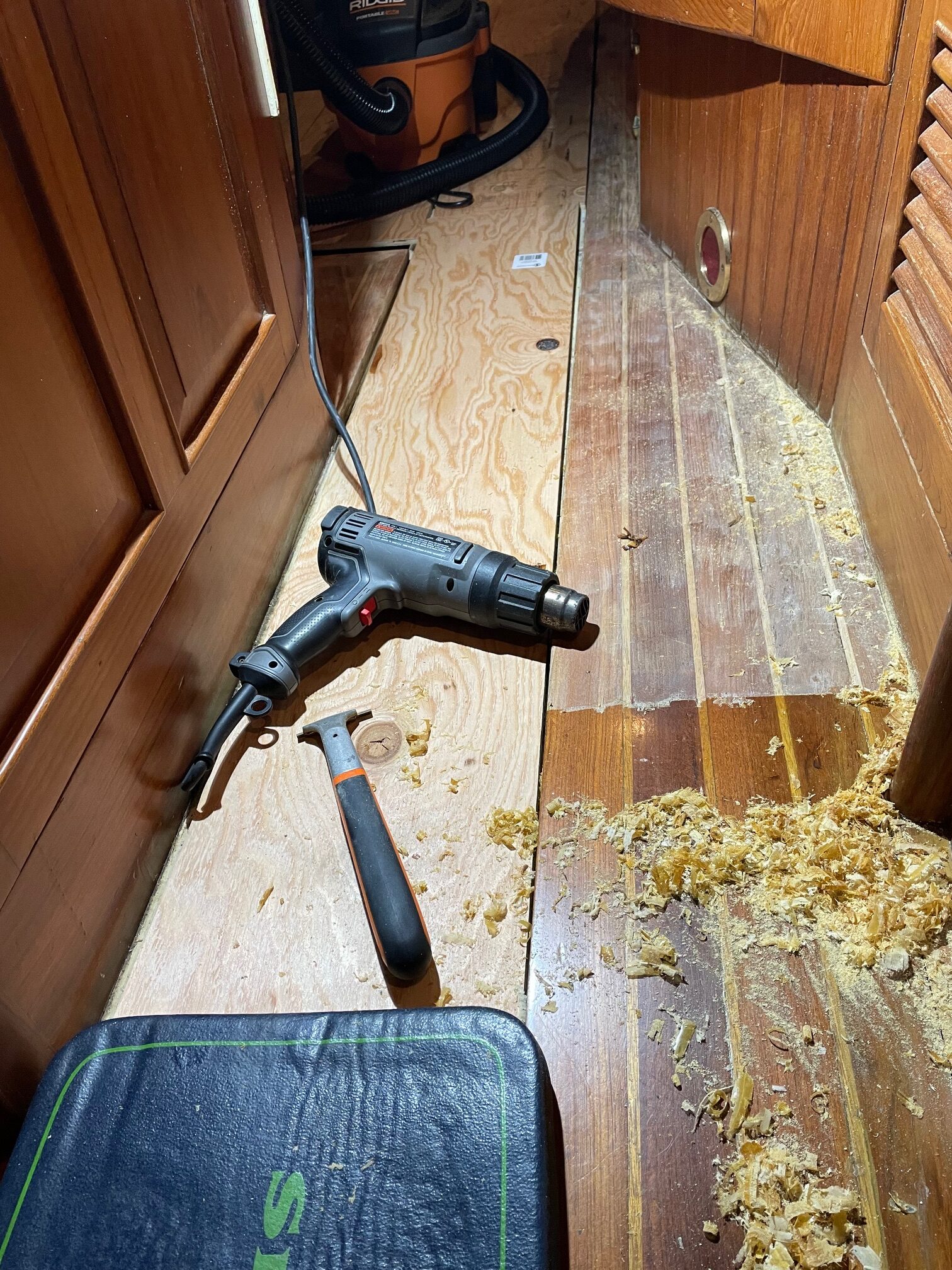
Use a heat gun and scraper to remove the old varnish
Use an orbital sander with 80 grit then 240 grit
Apply clear primer
Apply 6 coats of clear gloss
Apply 2 coats of clear matte
Polish and reinstall brass hardware
The holly on Apropos sole appeared yellow because of the tint in the varnish. After stripping off the varnish and sanding, the holly is almost white. The finishing I’m using (Awlwood primer and clear) should do a better job at keeping the holly bright.
Removing VarnishScraped & SandedReady for Primer
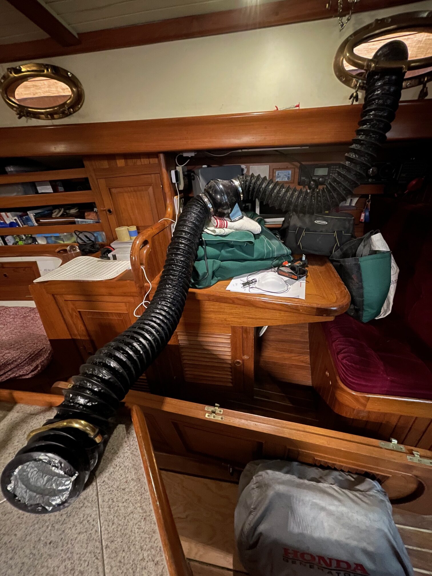
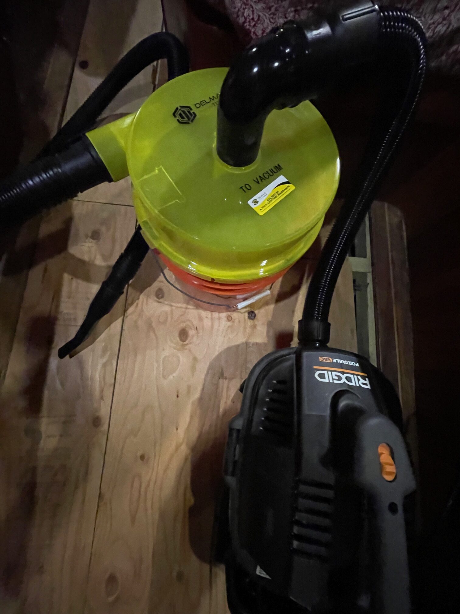
For the non-removable sections of the sole, the process was a lot more difficult. From a full sheet of plywood, I cut various shapes to take the place of the removed panels and make walking around easier. Heating, scraping, and sanding were messy. The orbital palm sander put dust everywhere. Goggles and a good respirator were important protections from dust and chemical fumes. When sanding, I ran a duct fan with 4″ hoses from the area where I was working, out through a port to the outside of the boat. At 195 cfm, this helped remove a lot of the dust in the air. I also used a good shop vacuum with a dust separator while scraping and sanding. I ran a dehumidifier and heater to get better climate control for working and applying finishes.
Duct FanDust Separator
Primer Coat
After final sanding and using compressed air to remove the fine saw dust, I applied a coat of Awlwood Clear Primer. This helps seal the wood and prepare for building the layers of Clear Gloss. Even though there was no pigment in the primer, it gave the teak a darker tone while still keeping the holly bright.
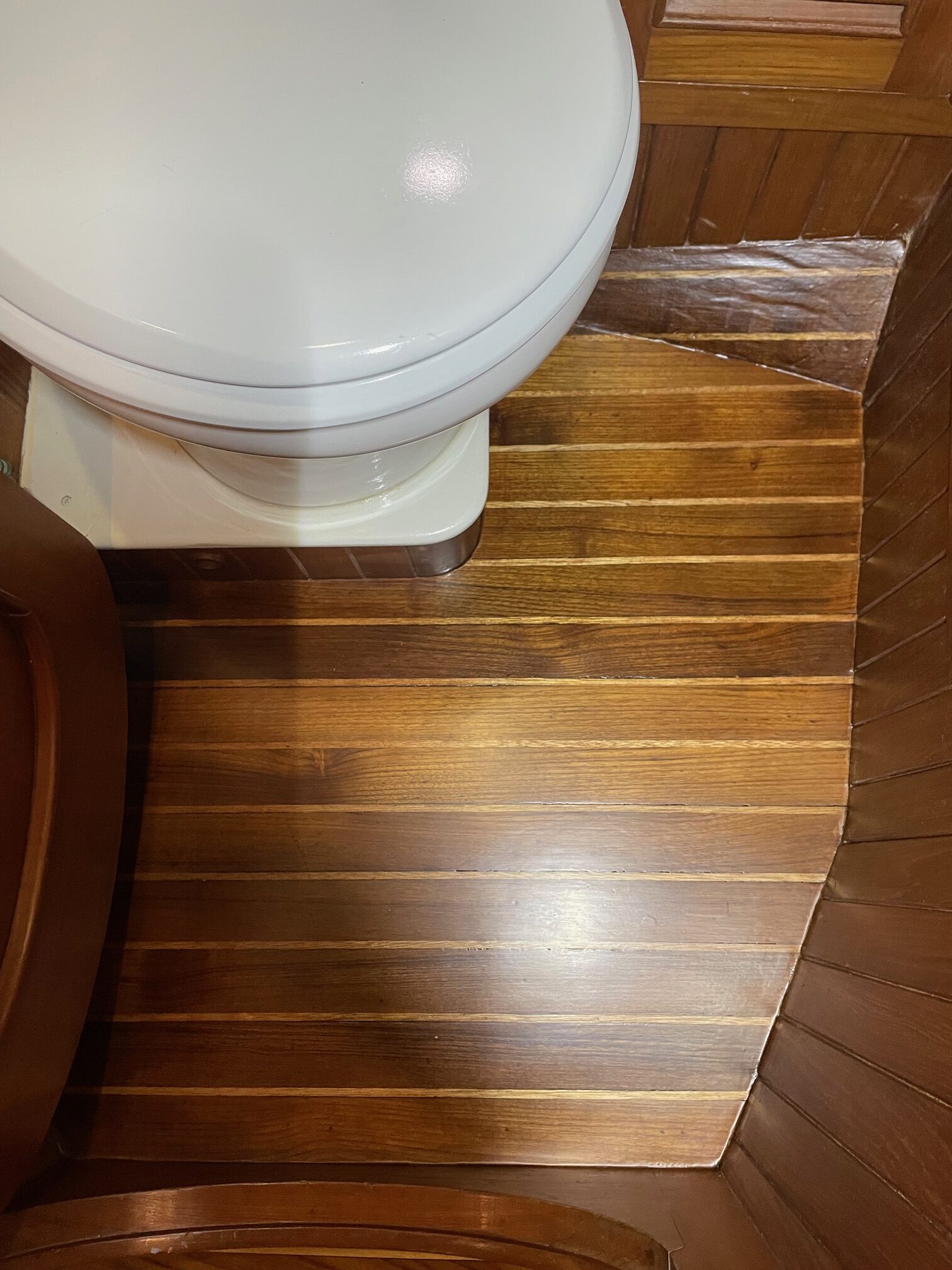
Clear Coats
After a light sanding of the primer, I applied 6 coats of Awlwood Gloss, sanding after every 2 coats. I used Awlwood Matte for coats 7 and 8 to give it a less shiny look and make it less slippery. Here’s a before and after photo of one of the panels.
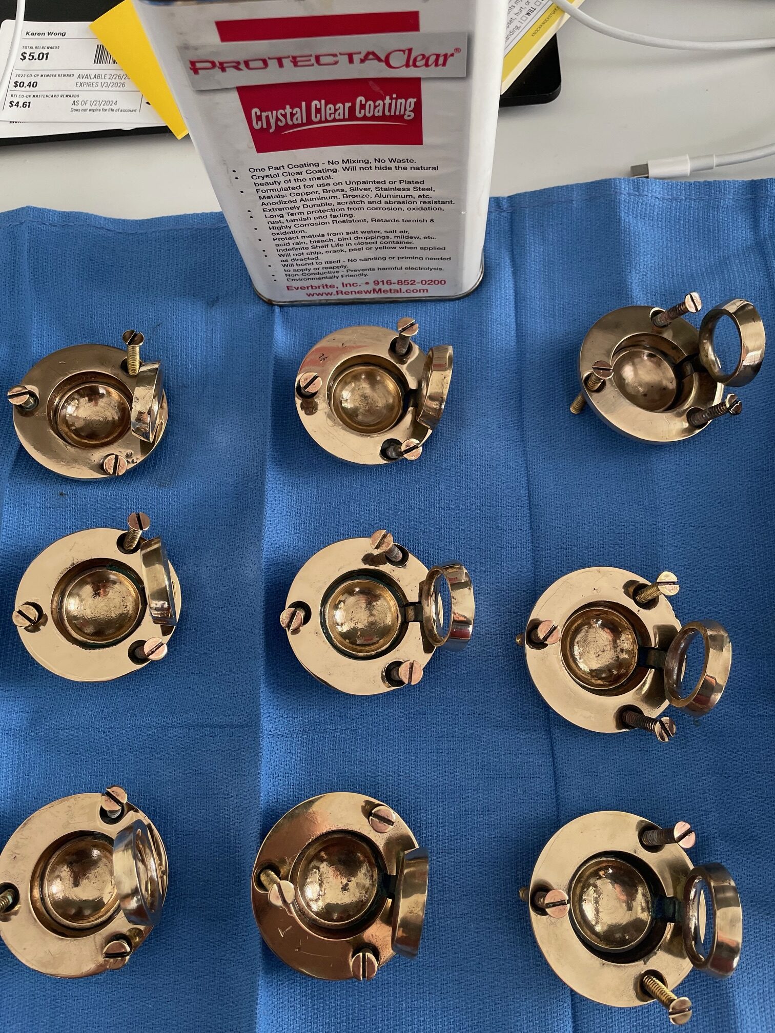
Brass Pull Rings
Using a wheel polisher with buffing compounds, I was able to make the brass pull rings shiny again. After polishing, I coated them with 6 layers of ProtectaClear. I’ve had good luck with using ProtectaClear on interior brass parts such as galley faucets and hatch hardware, but not sure how durable it will be on parts that will be walked on.
Conclusion
The project took about a month from start to finish. It was a lot of hard work but the results were very satisfying.
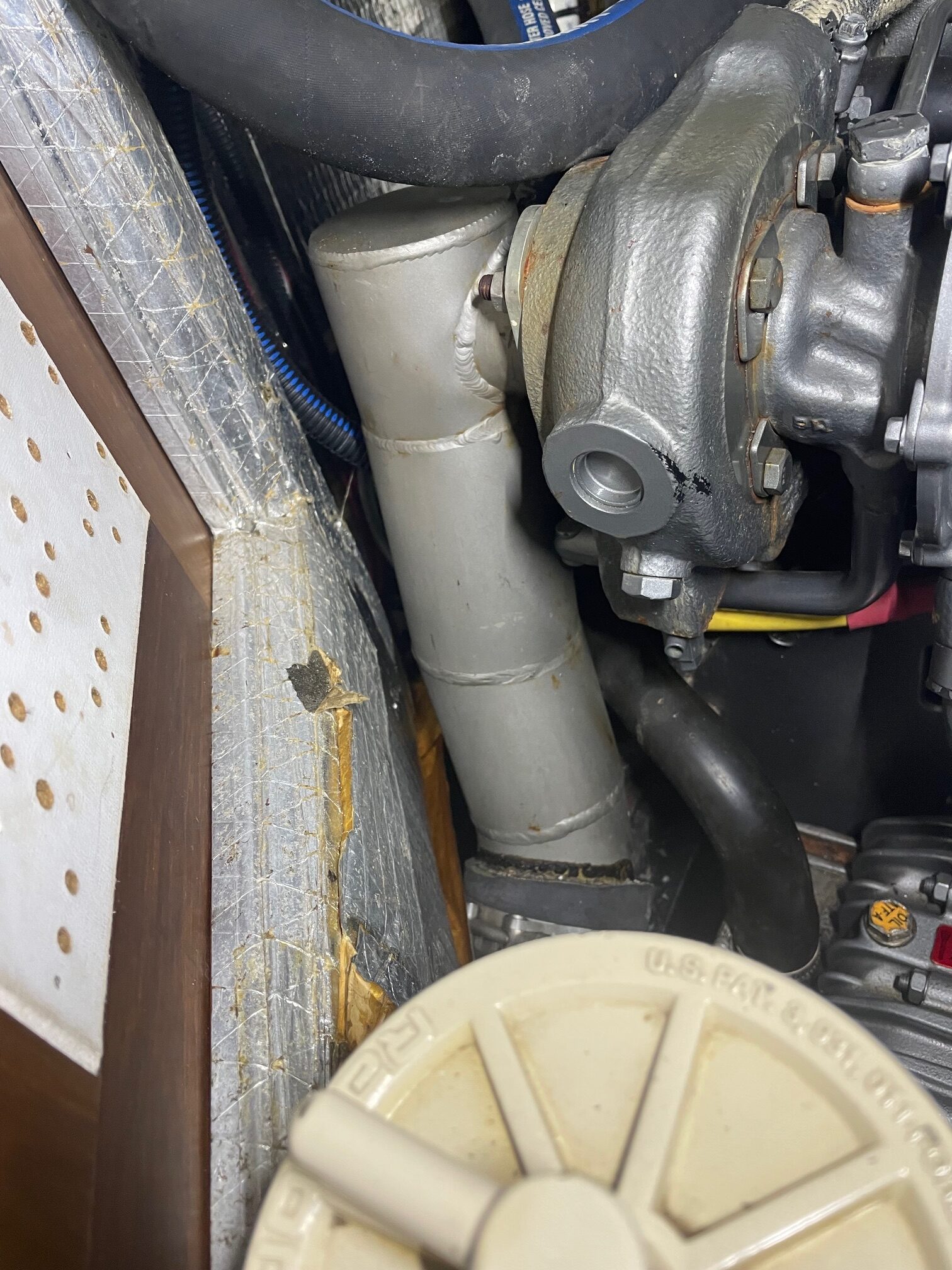
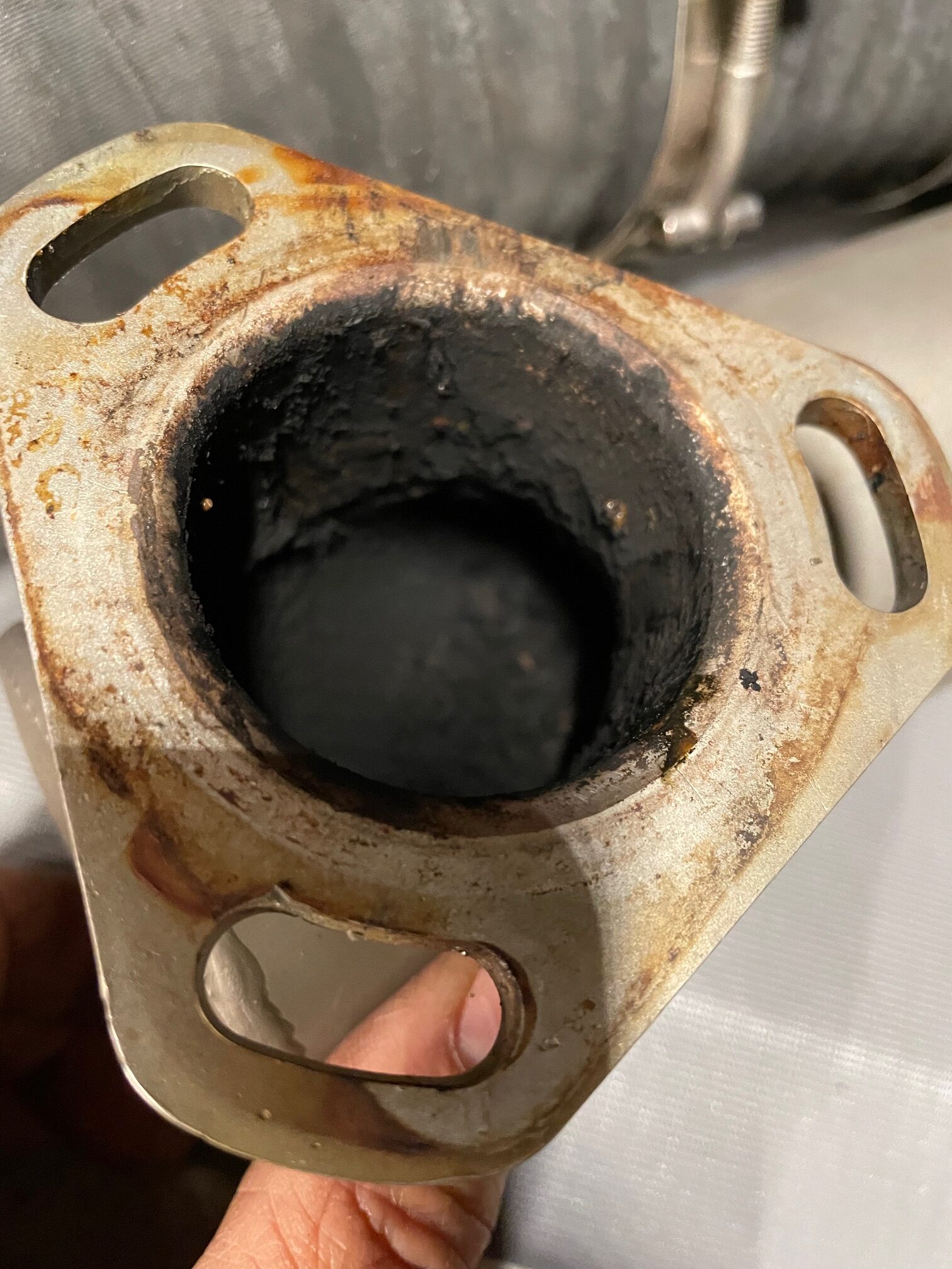
A mixing elbow is an external part on a diesel engine that combines the sea water (used for cooling the engine) with the combustion exhaust gases. The mixture is usually directed downwards into the bilge through a large diameter wet exhaust pipe leading to a thru-hull exiting the boat at the stern. An anti-siphon loop is somewhere in the exit hose to prevent water from coming in from the thru-hull in a following sea. Because of the harsh environment of hot gases and saltwater, mixing elbows have a lifetime of around 6-10 years and engine manufacturers suggest inspection every 3 years. OEM mixing elbows are typically made of steel and last a lot shorter time than ones made of 316 stainless steel.
The mixing elbow on Apropos was a stainless steel custom-made part that was 20 years old with 2850 engine hours. Space constraints in the engine bay required a custom part with specific bends and angles to clear the cabinetry. I periodically inspected the welds which are typically what fails first. It probably lasted so long because the boat has been moored in fresh water for 18 of the past 20 years. I also run the engine hard on my way back to the dock which helps clean out the exhaust elbow. Removing it was easy–3 bolts attaching it to the engine, the fresh water input hose, and the wet exhaust output hose. The 3″ diameter exhaust hose was only 30″ long, so I decided to slice the ends to make it easier to remove from the exhaust elbow. I also cut the other end which was attached to a fitting on the exhaust muffler. I bought a new 34″ hose (Trident-Flex) at Fisheries Supply for half price since it was a remnant, and used an angle grinder with a cutting disc to cut it to the correct length.
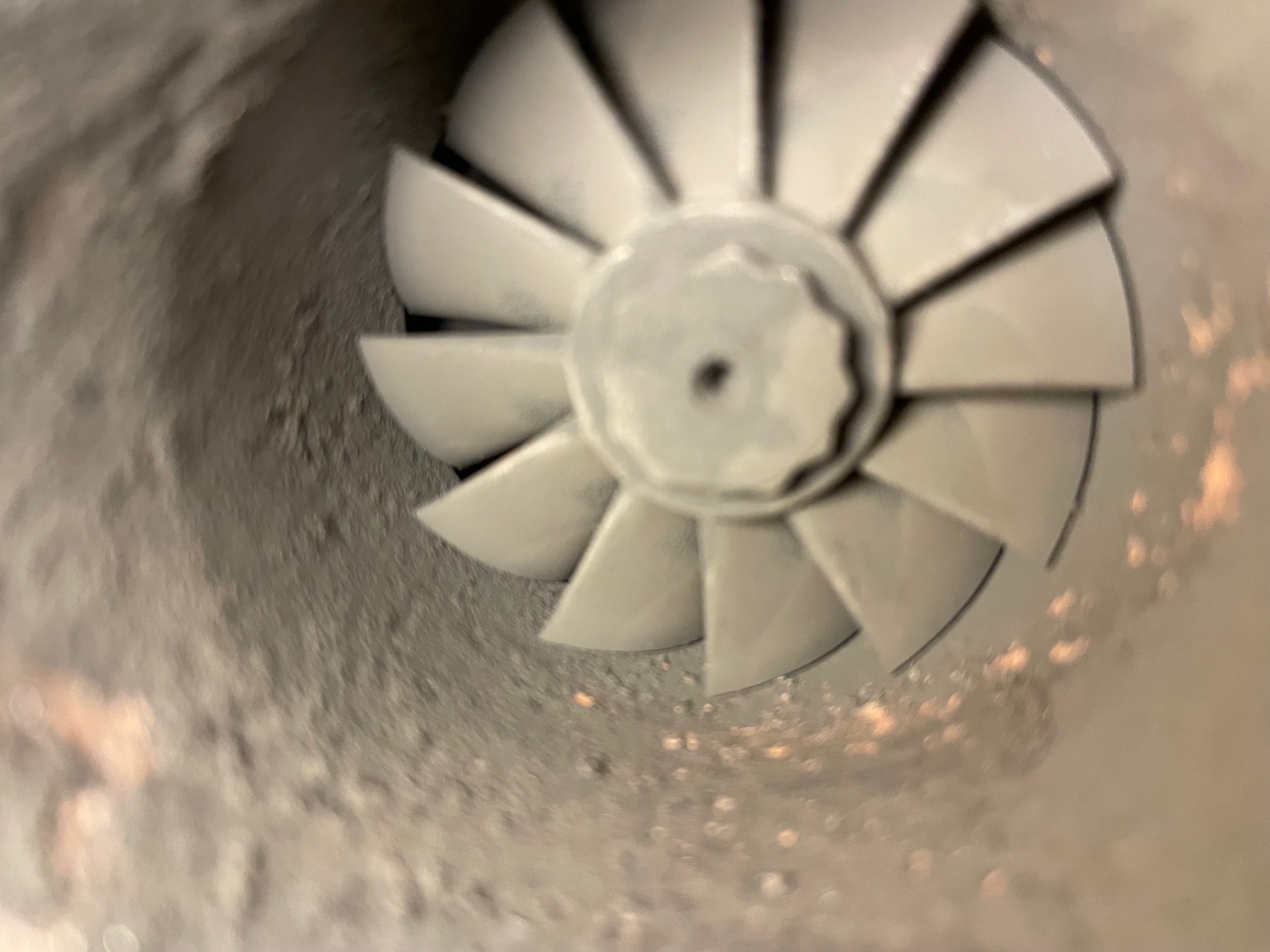
Original ElbowTurbo Fan (before cleaning)Old Elbow
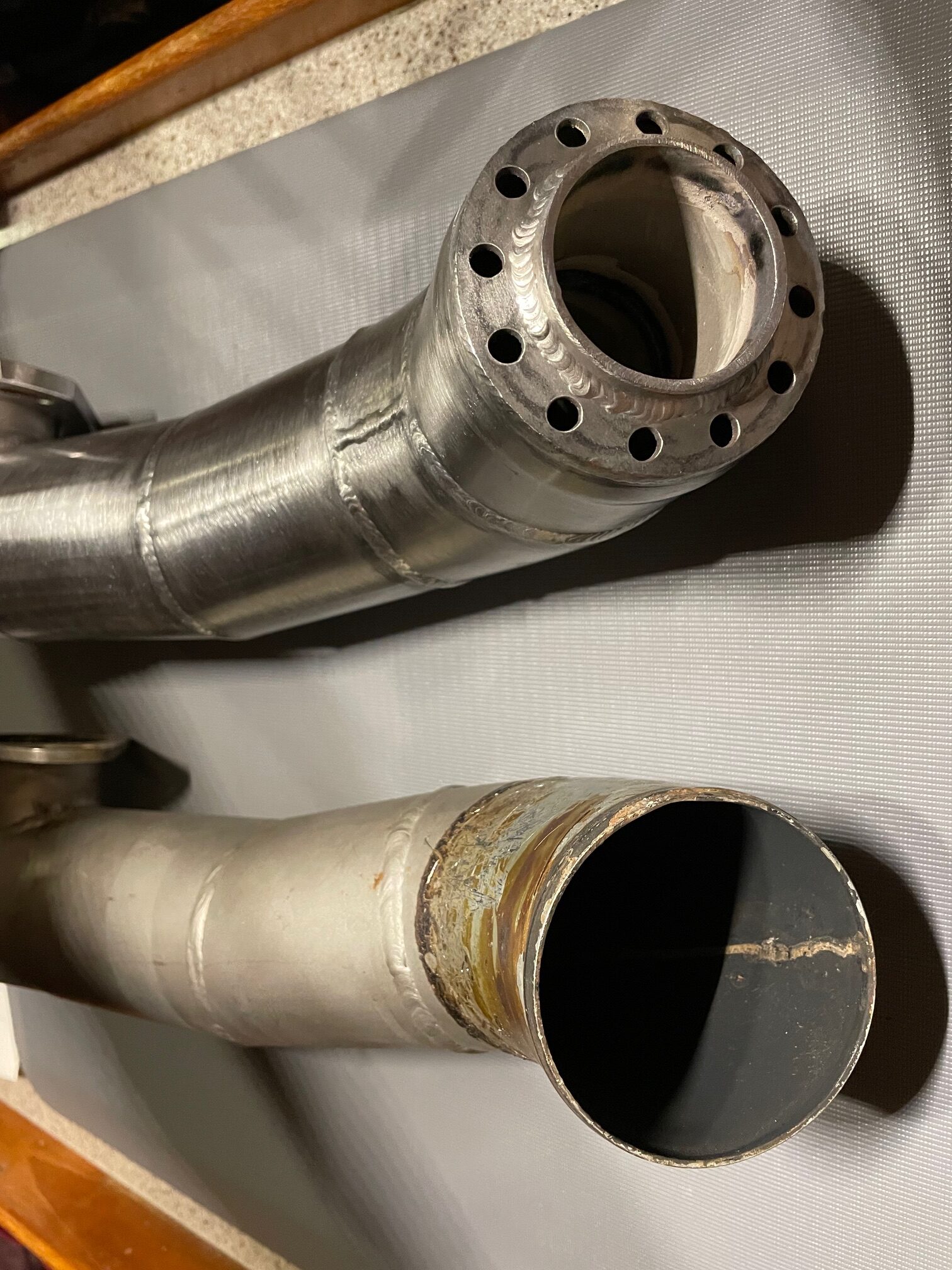
I delivered the old part to National Marine Exhaust (Marysville, WA) for them to duplicate. A week later I had the new exhaust elbow. It’s made of 316L (low carbon) stainless steel. Something they did different was to run the inner pipe (for exhaust) all the way to the output end. In the original part, the inner pipe only went 6″ from the sea water inlet. I guess the new design would cool the hot exhaust gasses more before they are combined with the sea water at the beginning of the wet exhaust hose.
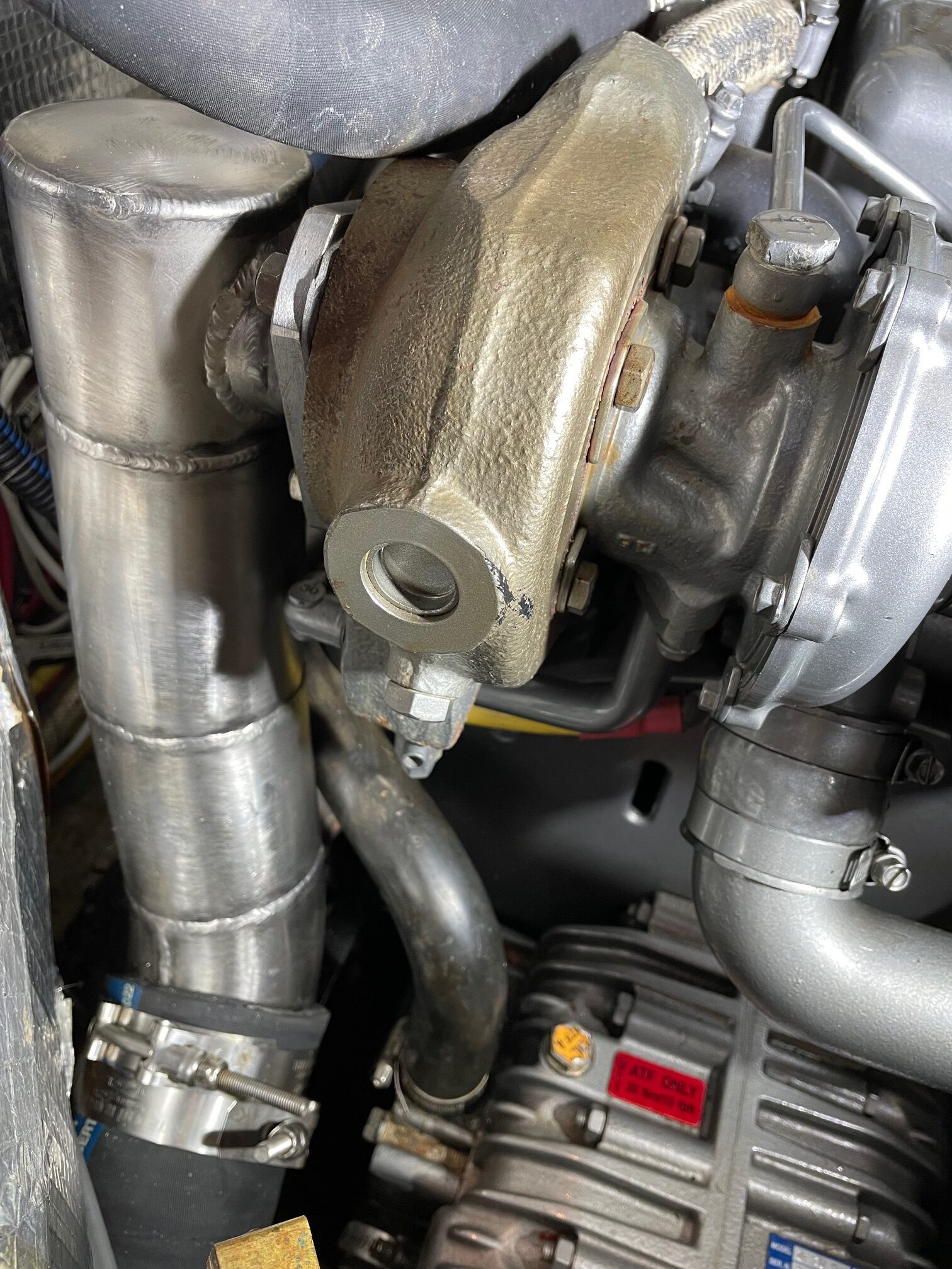
Installing the mixing elbow and new wet exhaust hose was a little harder than removal. I chose a 30 deg F day so the boat inside temperature was in the 40s. The first thing I did was to use bronze wool on the surface where the elbow attaches to the engine exhaust manifold to make it smooth for the fiber gasket. The Trident-Flex is anything but flexible, especially when cold. I warmed it up a bit using a heat gun, but it was still a struggle trying to bend it while fitting the ends onto the muffler and exhaust elbow. After a few attempts, I decided it would be easier to attach the hose first to the muffler using the 2 heavy duty ss hose clamps, then attach the other end of the hose to the mixing elbow, then attach the mixing elbow to the engine while bending the hose (the hard part). Eventually it all went back together. The final step was to run the engine to check for any leaks.
The solar panels that I had installed on Apropos were now 12 years old. They consisted of 2-85W, 2-95W, and 1-135W panels for a total of 495W. PV cells and solar panels have come a long way in 12 years. Increases in efficiency, flexible panels that can be walked on, bi-facial panels and better solar controllers are some of the changes that have occurred over the past years. Also, the price of solar cells have decreased dramatically.
The old solar panels were aboard Apropos during the 2014-15 trip to the South Pacific. The 2-85W panels sat on the deck against the butterfly hatch port and starboard, 2-95W panels were mounted outboard the lifelines port and starboard, and a 135W panel atop the dodger. The 2 on the deck were easily moved while at anchor to either side depending on the sun position. The system worked well and we were able to run all the electronics and have refrigeration and watermaker (run only with engine). We didn’t use autopilot (windvane was used instead) and had to shut down the freezer due to its frequent cycling.
There were several goals in upgrading the solar. More total PV watts, better placement of panels, better panel adjustments, and easier/quicker removal of panels from outboard mounts.
The new solar panels are 2-200W bifacial monocrystalline. Bifacial panels have additional, lower-grade solar cells on the backside of the panel to increase the efficiency/area. Most rooftop mounts can’t take advantage of bifacial panels, but the outboard mounts on a boat are ideal for bifacial panels where UV rays reflect off the water and hit the backside. The new 200W panels are approximately 30″ x 54″, 50% bigger than the 95W panels and 100% more wattage.
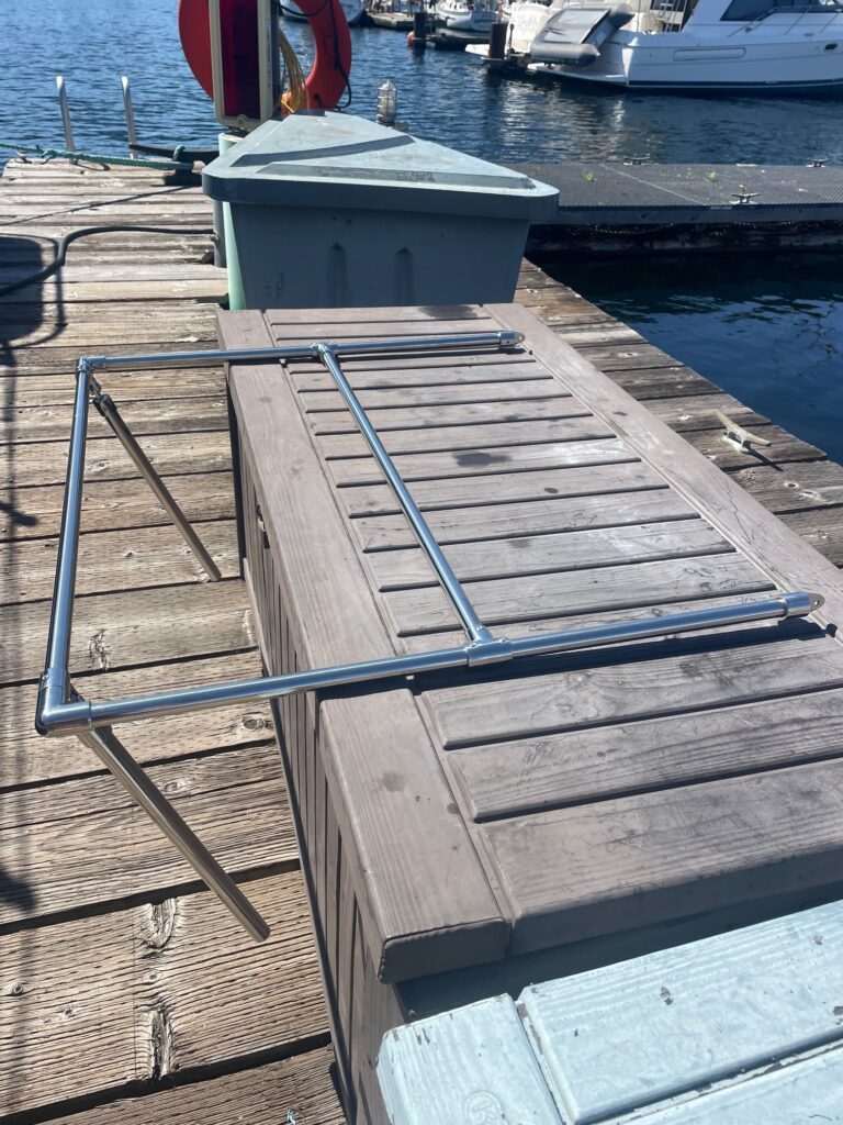
Mounting
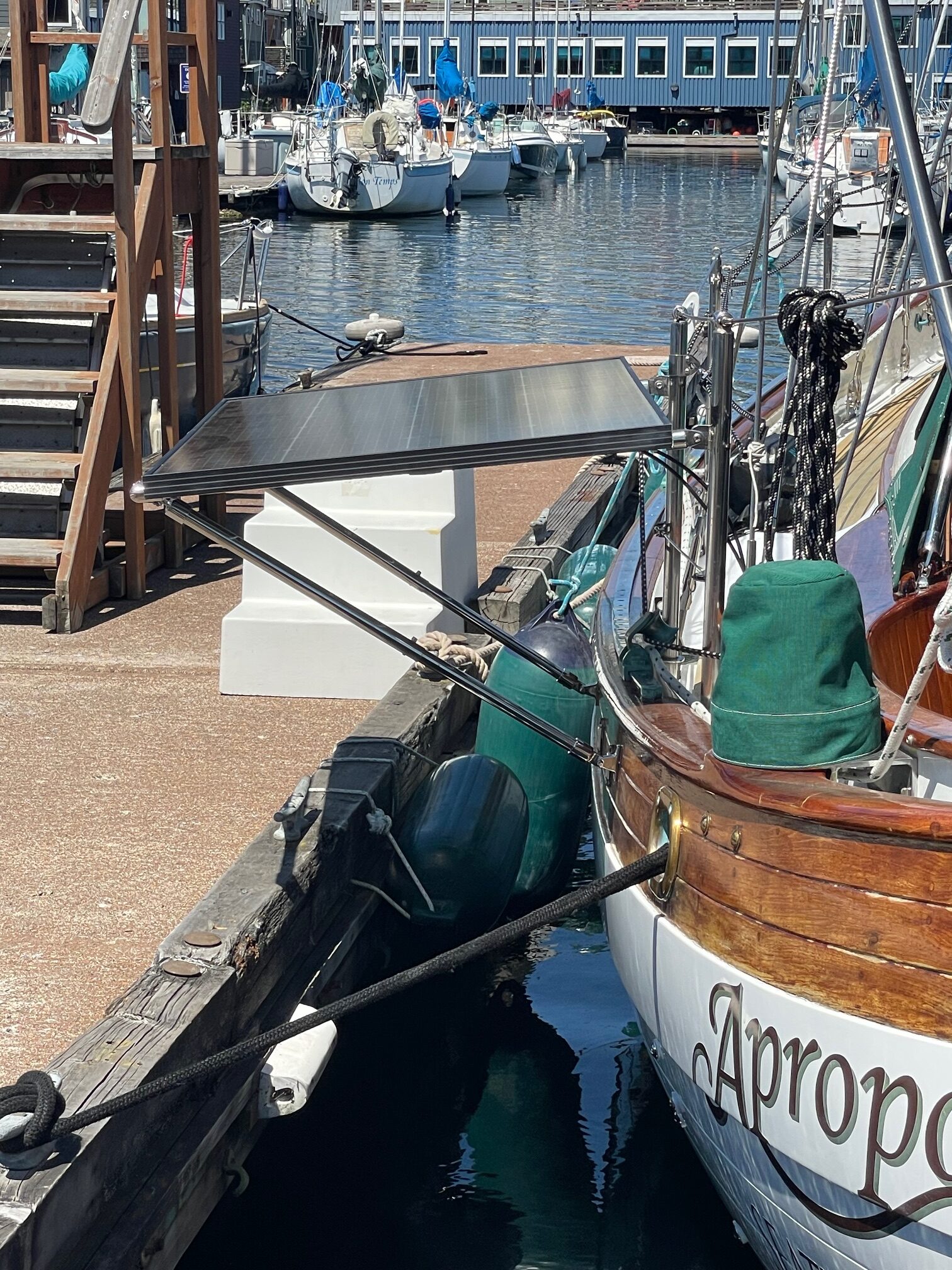
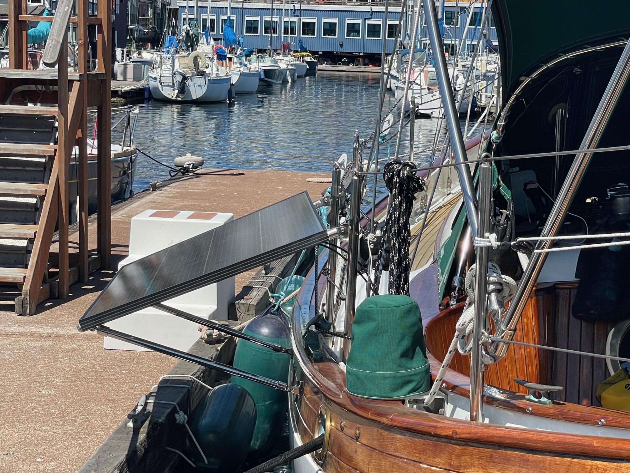
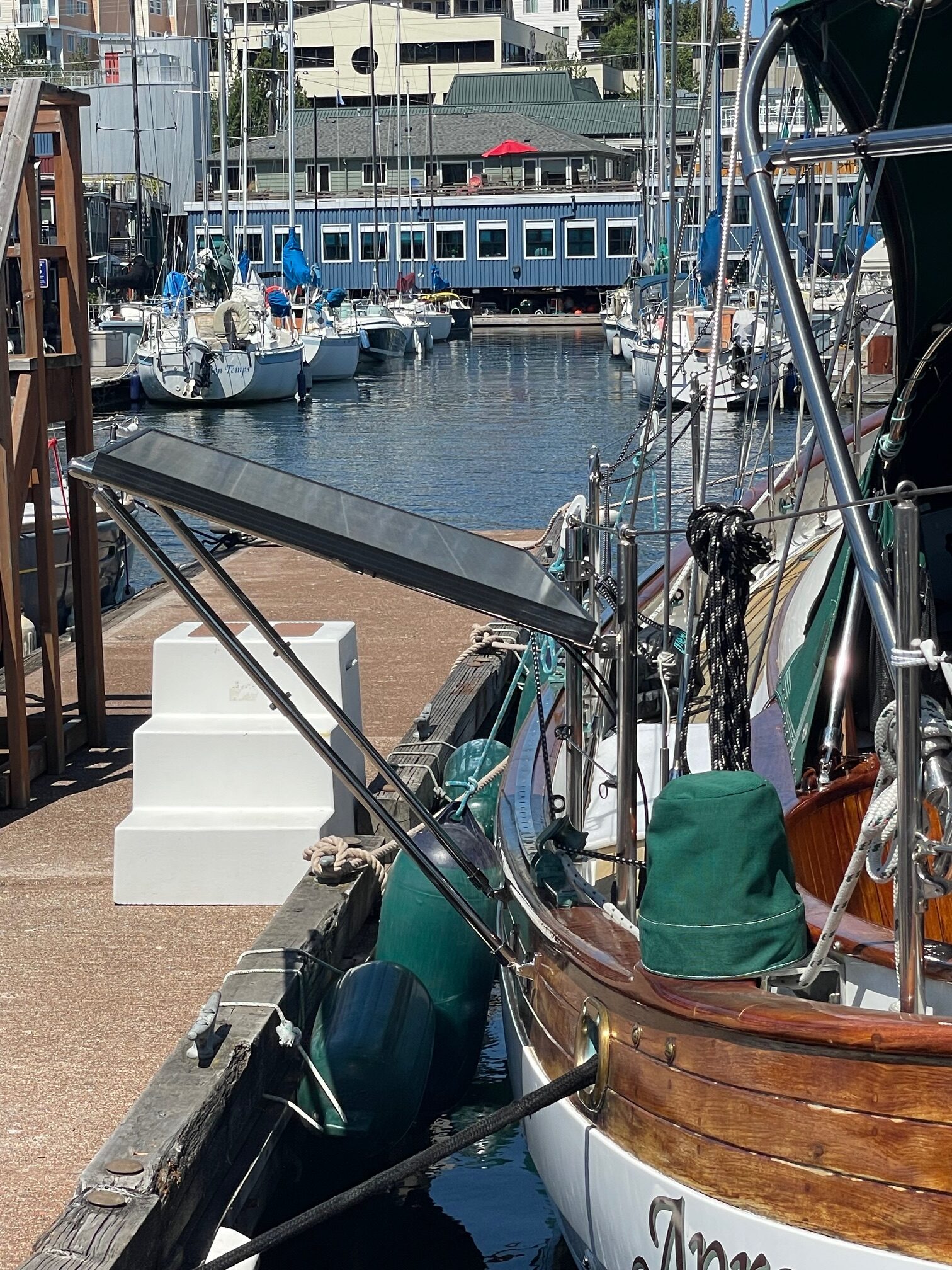
The increased size and weight of the new solar panels required a stronger mount. I built similar U-shaped frames out of 7/8″ stainless steel tubing as last time, but this time included an extra horizontal arm for better support. I also went from using a single strut to using 2 struts that support the frame to the hull. The frame attaches to 2 stanchions using spring pins, same as before. Two goals I had for the mount was to make the solar panels easily removable, and to make the panels adjustable. I decided on 3 settings– a 6 degree off horizontal, a 23 degree tilt away from the boat, and a 20 degree tilt toward the boat. This is accomplished by using 1″ thin walled tubing and 7/8″ thick walled tubing for the two struts. This allows the 7/8″ tubing to slide inside the 1″ tubing. The 23 degree tilt away from the boat is set by the length of the 7/8″ tubing (24″). The 6 degree horizontal position is accomplished by inserting a pin or bolt into a hole in each strut. Likewise, the 20 degree tilt towards the boat by inserting a pin into the 2nd hole in each strut. The panels can also be moved into an up position to get them out of the way during docking or going through locks.
6 degree23 degree-20 degree
The panel position is made easier to set with the addition of a line that is led from the panel, through a low friction ring lashed to a shroud, to a cleat on the dodger. I marked the line for the different panel positions. This makes it a 1-person job to change the panel angle or stow in the up-position.