Although my 20+ year old navigation electronics were all functioning, it was time to update to newer technology and features. While attending the Seattle Boat Show in February, I compared different brands and decided to go with the latest B&G (Navico) equipment for the chartplotter and radar.
Old Equipment
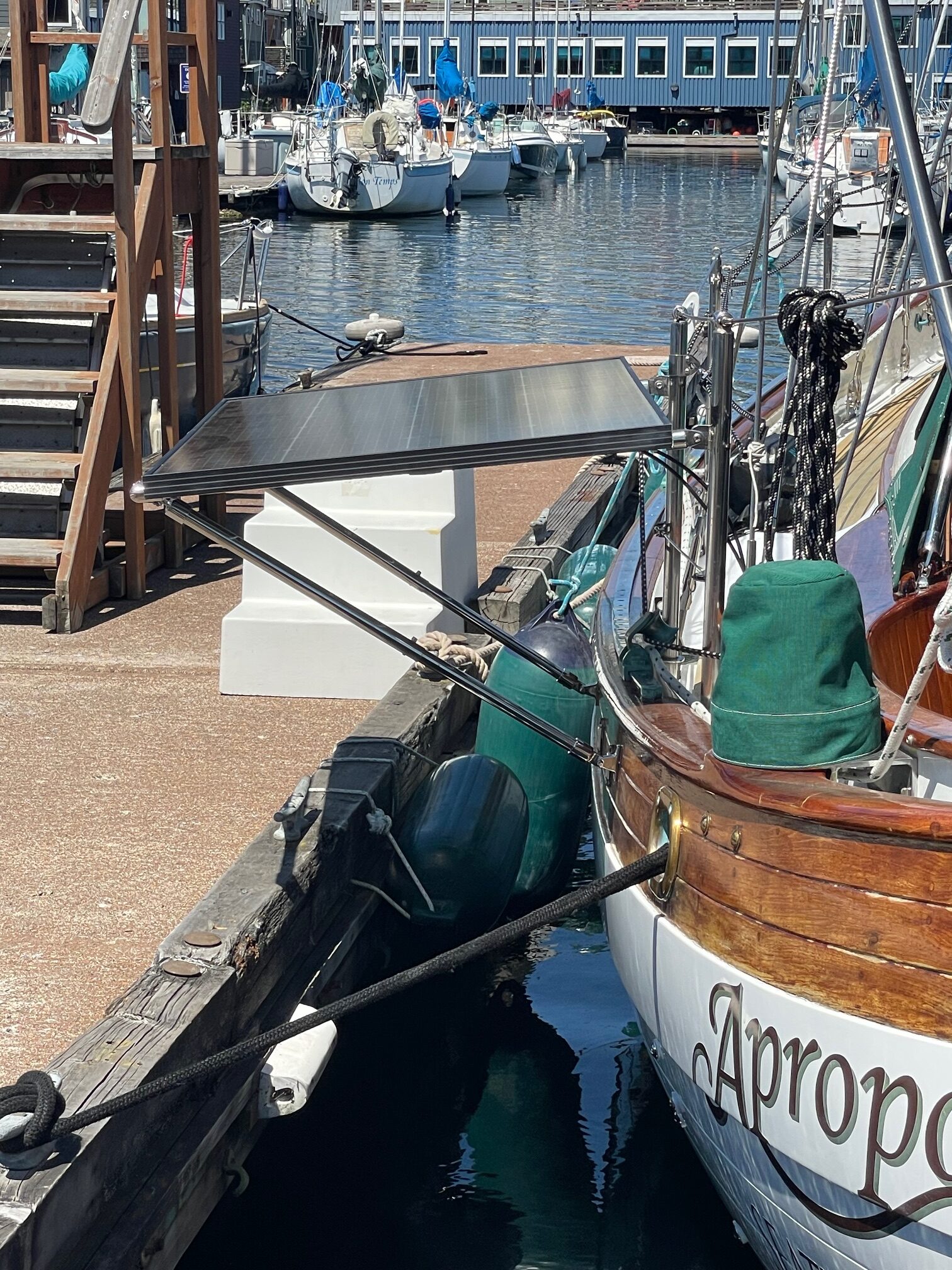
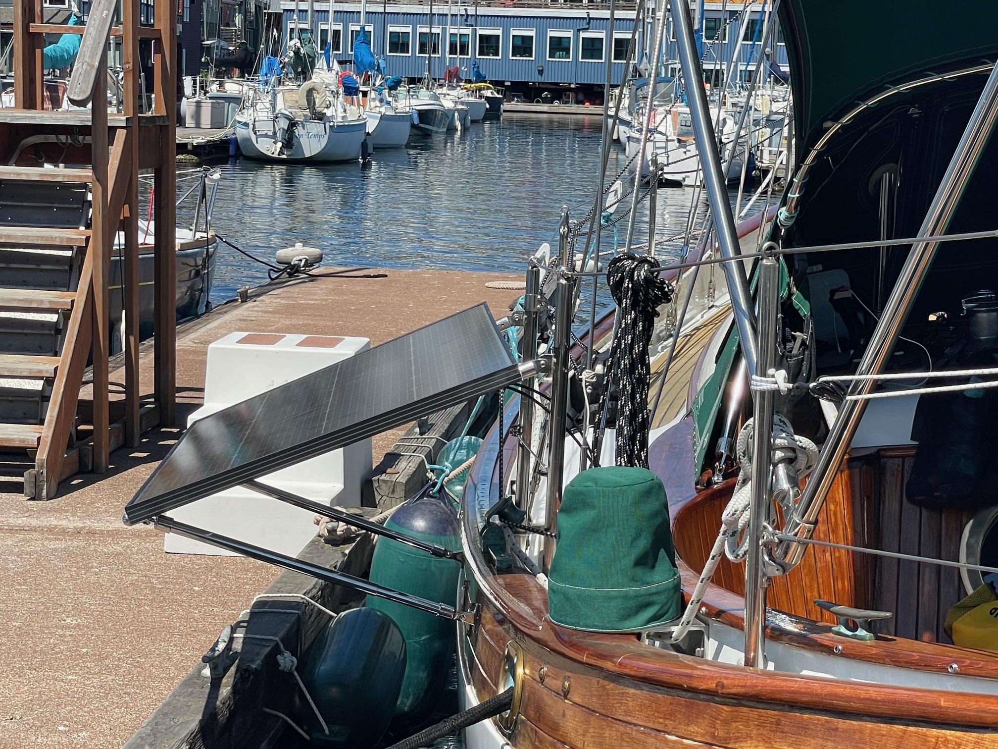
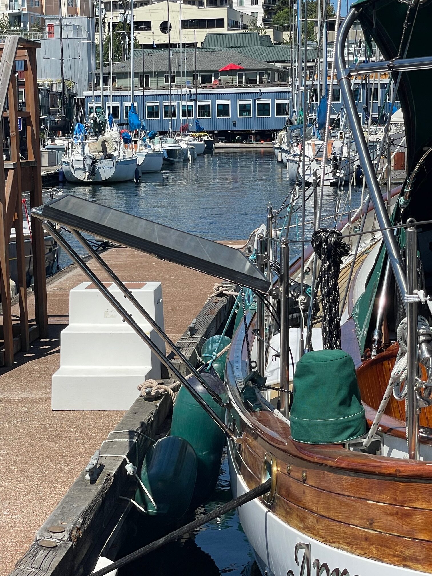
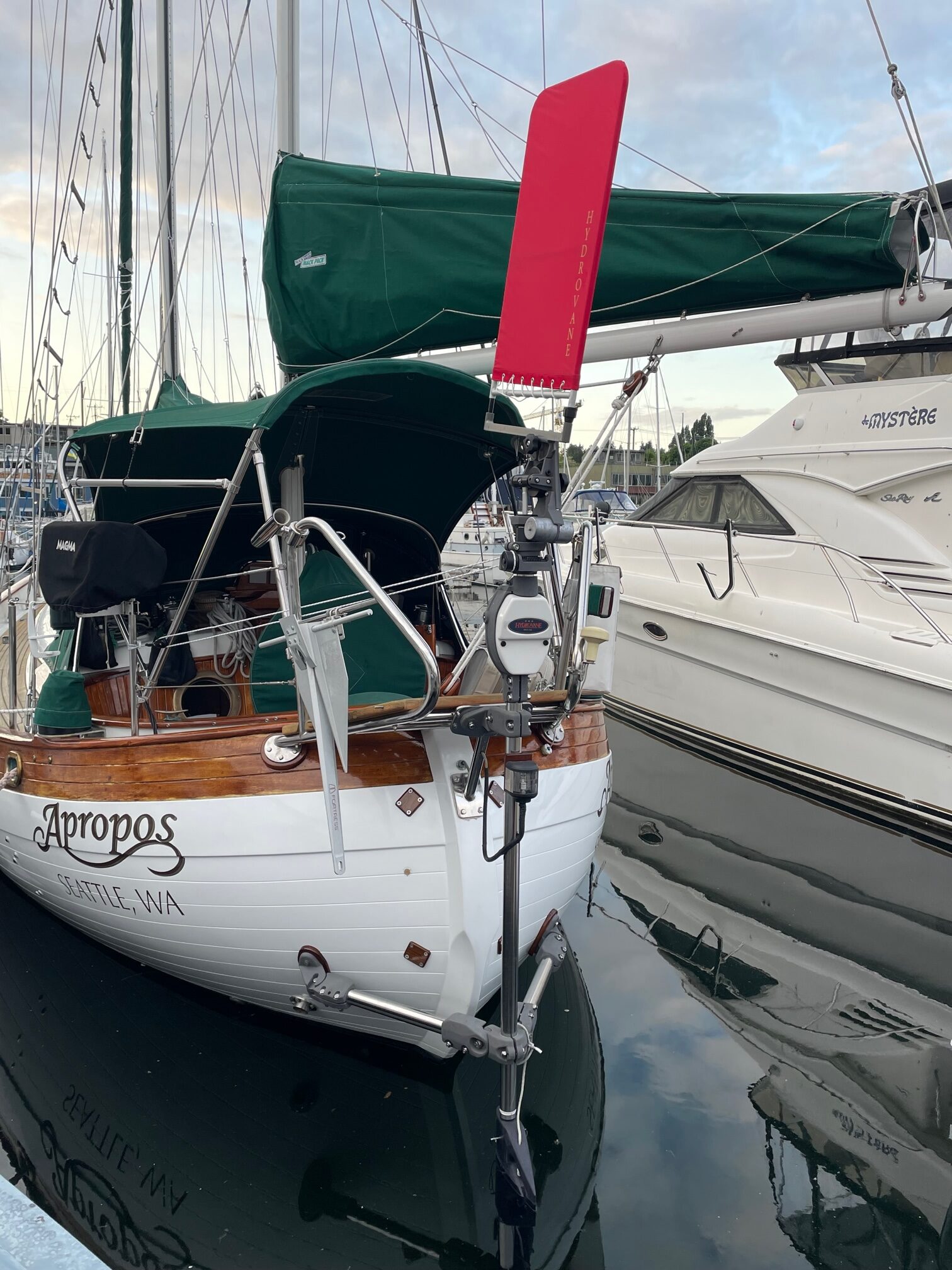
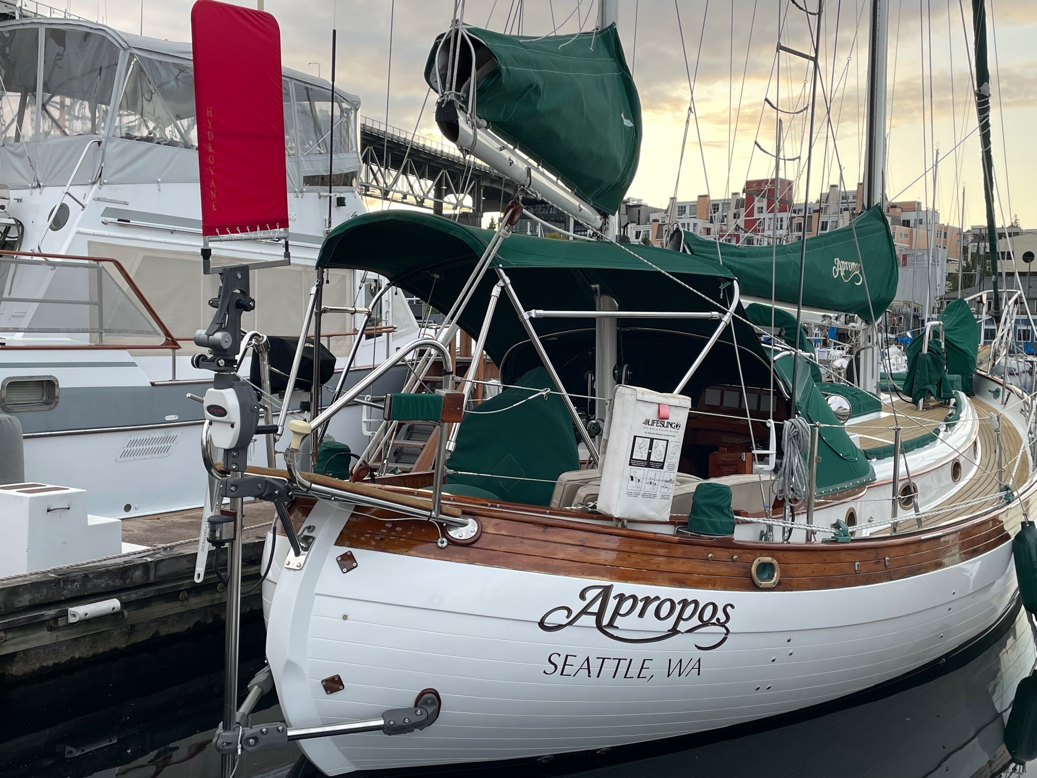
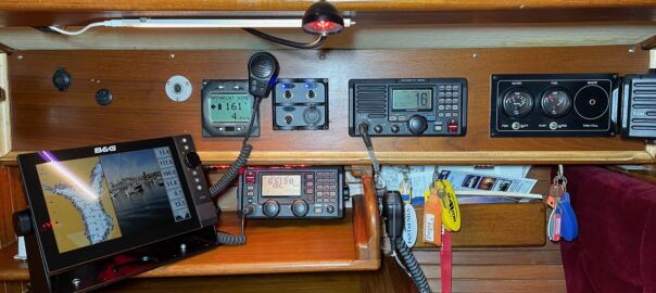
When I bought Apropos in 2004, most of the electronics were brand new (chartplotter, vhf, inverter/charger, autopilot, wind/speed/depth transducers & instruments). I added AIS, SSB, another chartplotter (Garmin 547XS) at the helm, and solar panels & controller in preparation for an offshore trip. More recently, I replaced the entire charging system with Victron equipment when I converted to Lithium (LiFePO4) batteries. But the Raymarine chartplotter & radar were still old and outdated equipment, although still working.
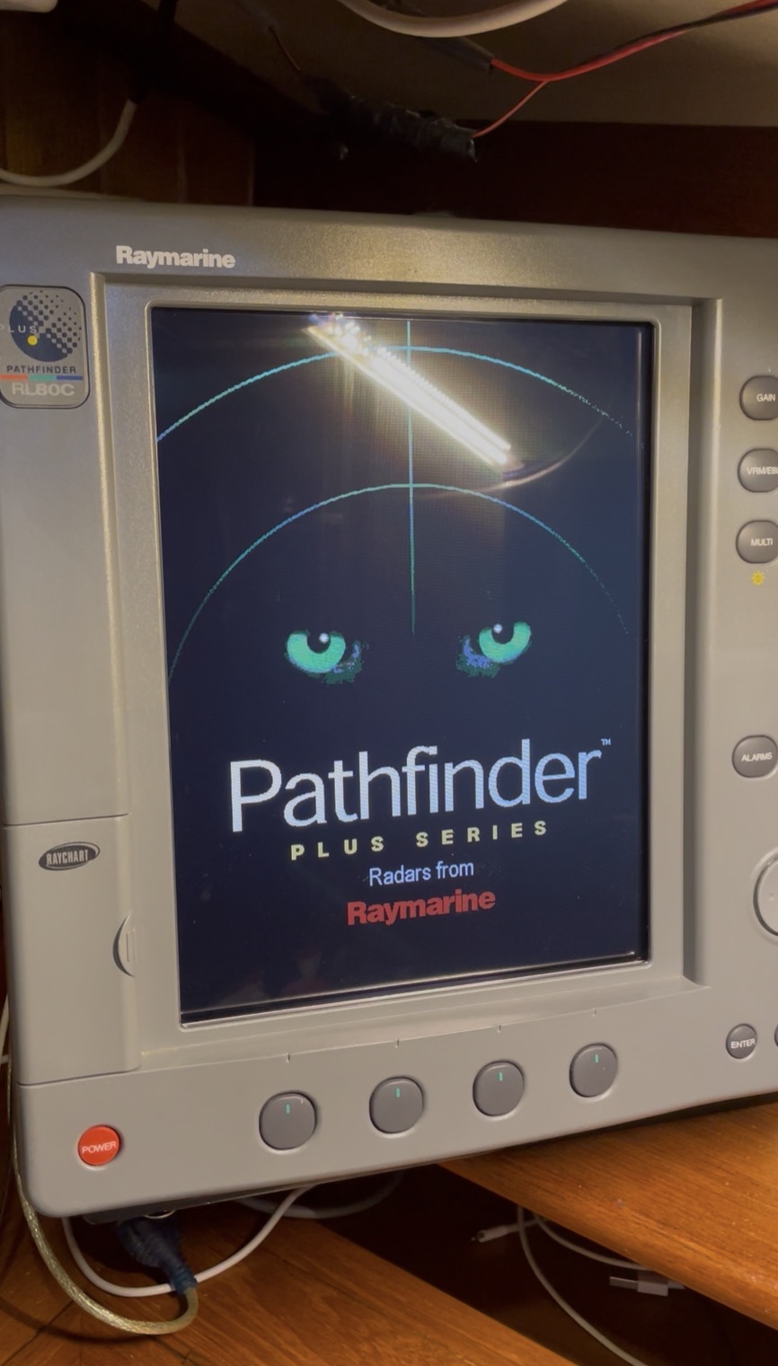
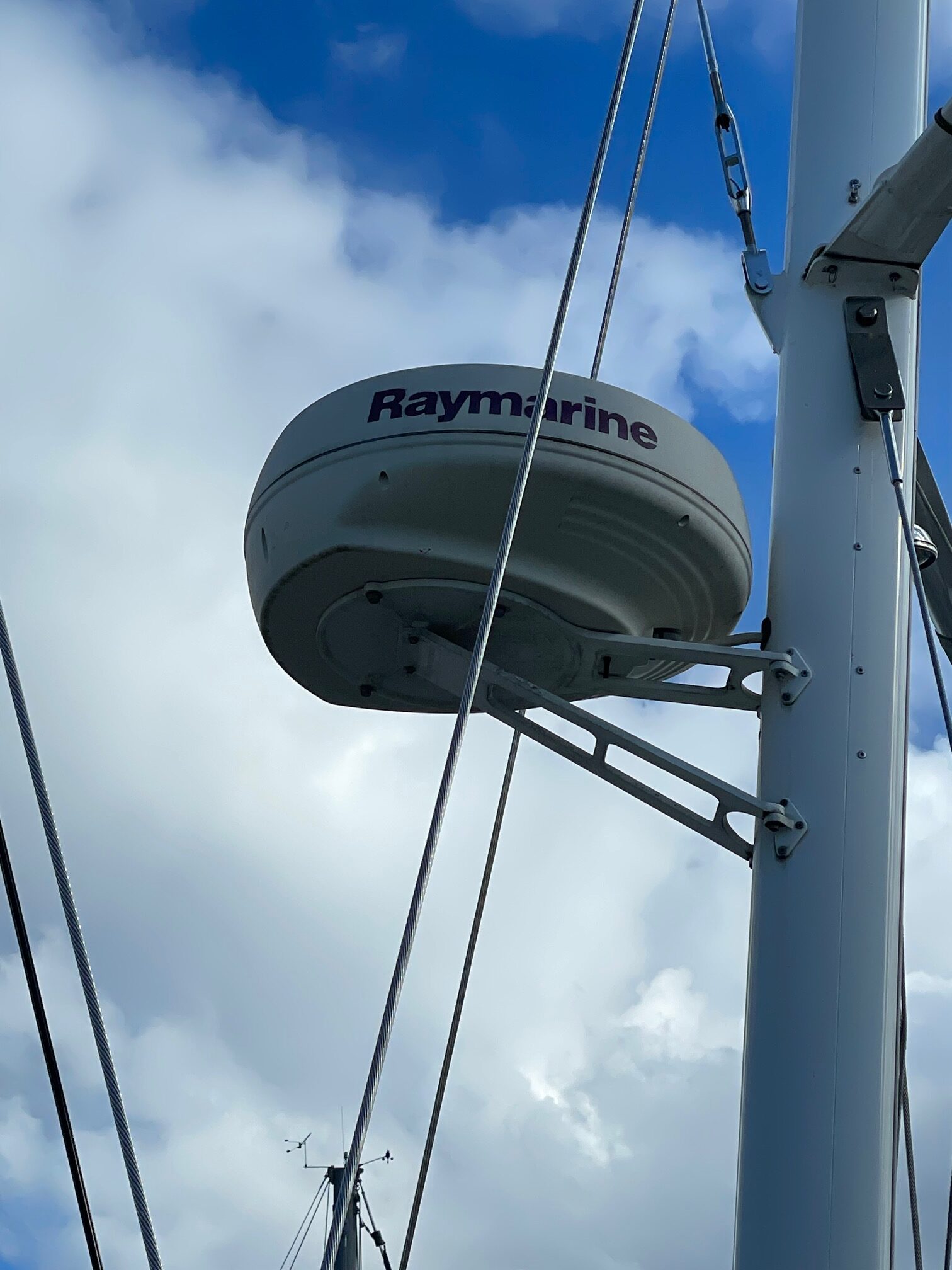
The Raymarine Pathfinder Plus (12″ screen) was mounted at the nav station and tied in with the Raymarine analog radar mounted on the mizzen mast. This system worked great for Puget Sound cruising especially in foggy conditions where the radar was our eyes. But we discovered when offshore that the radar was far too power hungry to run full time and even the chartplotter was seldom used since we had a smaller Garmin chartplotter at the helm.
New Equipment
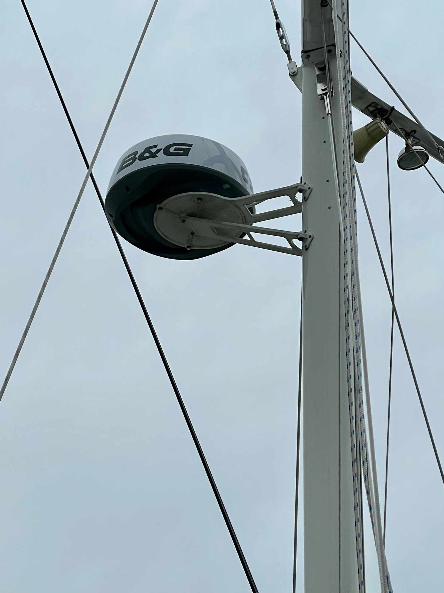
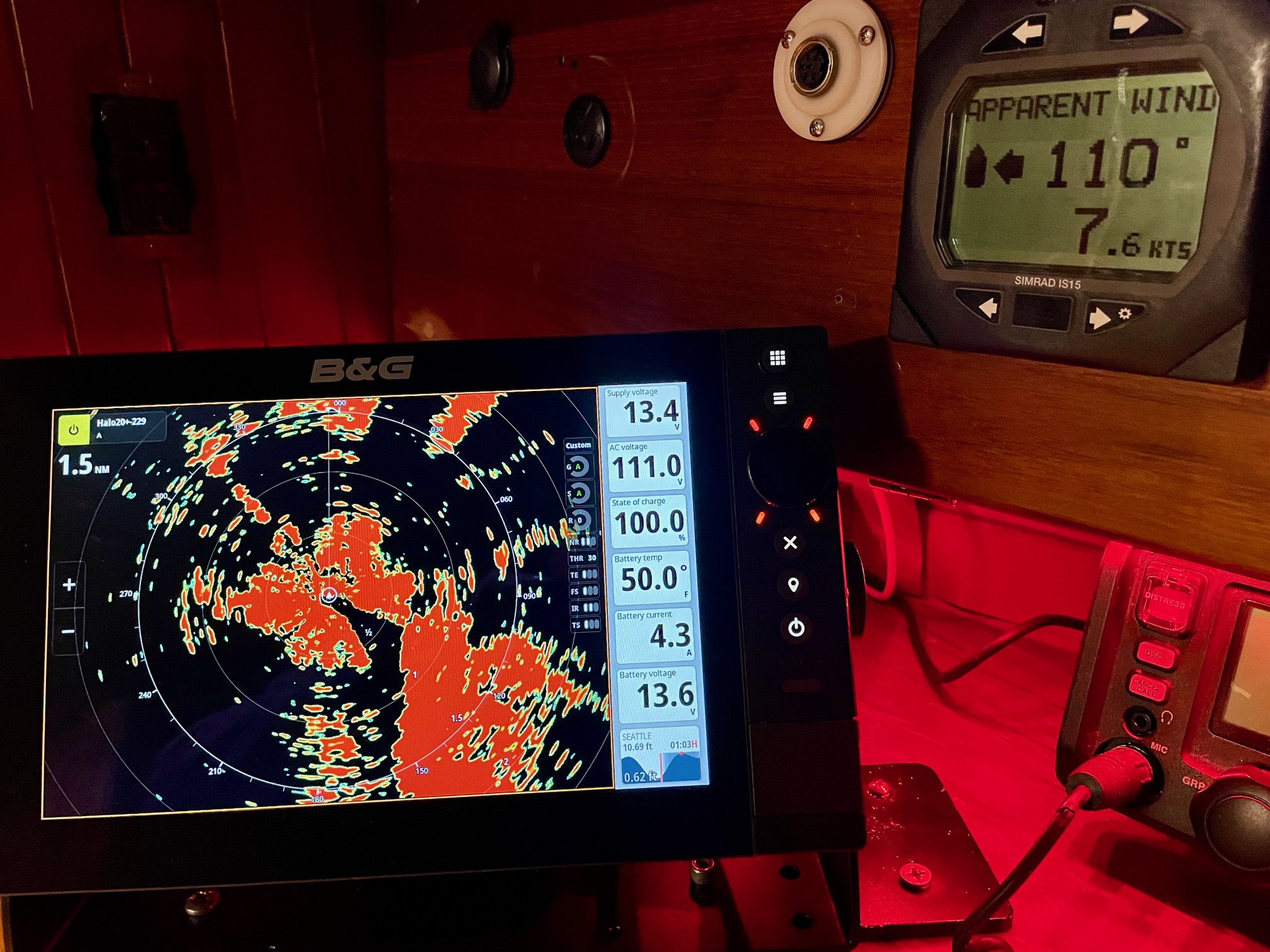
Besides updating for reliability reasons, I also wanted more features with the chartplotter and radar. I decided on the newest B&G chartplotter called Zeus SR paired with the B&G Halo20+ radar.
Zeus SR Features
- High definition SolarMAX™ IPS touchscreen, viewable from all angles, even with polarised glasses
- Separate modes for Cruising, Racing and Anchoring
- Award-winning sailing features like SailSteer™, LayLines, Routes and StartLine
- Compatible with C-MAP® DISCOVER® X and REVEAL® X charts
- C-MAP®-powered Safety Alerts
- Full integration with HALO® radars, B&G® Sailing Processors, Autopilots, Triton2 and Nemesis® instruments, wind sensors and more…
- B&G® App integration with 12 months premium subscription when registering a C-MAP® X Chart.
- Wi-Fi 5, Gigabit Ethernet & NMEA 2000® networking
- Support for up to four IP video cameras
- Set-up Wizard to get you up and running quickly.
Halo20+ Features
- 36 nm range from a compact 20-inch dome
- Advanced pulse compression technology with beam sharpening
- Simultaneous Dual Range operation sees both far and near
- Ultra-fast 60 RPM operation at ranges up to 1.5 nm
- VelocityTrack™ Doppler technology to avoid collision
- Easy operation with harbour, offshore, weather and custom modes
- MARPA target tracking (up to 10 targets, 20 in dual range)
- Ready instantly from standby
- Low power consumption
NMEA 0183 and NMEA 2000
Before installing these pieces of equipment, I had to make a big change to the boats’ communication network. Boats like Apropos built in the 1980’s used the NMEA 0183 standard. NMEA 0183 is an ASCII-based serial communication protocol used to connect marine electronics–such as GPS, depth sounders, autopilots, and chartplotters–allowing them to share navigation data. It uses a “single talker, multiple listener model.”
NMEA 2000 (N2K) is a standardized, high-speed digital network for marine electronics, based on the CAN bus protocol used in automobiles. It connects multiple sensors (GPS, wind, speed, depth, battery, engine) to displays, allowing data sharing across brands. Key benefits include easy “plug-and-play” installation, reliability, and real-time, bi-directional communication among devices.
Since Apropos’ sensors (depth sounder, speed, rudder position) and 5 display instruments are all NMEA 0183 devices, I decided to go with a hybrid system that retains some 0183 devices but adds NMEA 2000 capability for new equipment that supports only NMEA 2000. As my old 0183 equipment (AIS, VHF, sensors, display devices) fails, it will be easy to buy the new 2000 version and simply plug it in.
What’s meant by “plug-and-play”? An N2K system has a backbone, which is a 5 conductor wire that runs throughout the boat and can easily be extended as needed. It has a 120 Ohm terminator on each end, a power T-connector anywhere along the backbone for supplying 12V power, T-connectors which are used to connect individual devices to the backbone, and drop cables, which are short cables (6 meters max) connecting devices to the T-connectors. Here is a diagram of Apropos N2K backbone (the backbone is the thick black line, the power T is red, the T-connectors are yellow, the terminators are light blue, the green boxes are NMEA 2000 equipment, and the purple boxes are NMEA 0183 equipment).
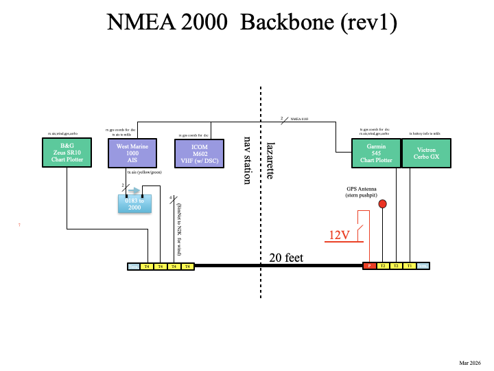
A dalemma exists when you want to display information that comes from NMEA 0183 equipment on N2K equipment. In my case, I want to see the AIS (Automatic Identification System that tracks other vessels and lets them see you) output on the Zeus chartplotter. Since the AIS puts out 0183 data and the chartplotter accepts 2000 data, a piece of equipment called a Gateway can be used that converts 0183 to 2000 and vice versa. This is shown in the above diagram with the light blue box.
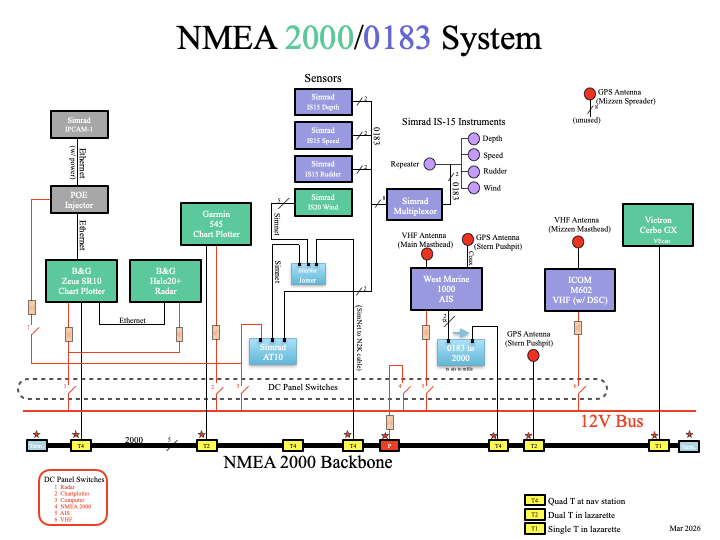
Here’s another diagram that shows more detail of the NMEA 2000/0183 System on Apropos (the green boxes are NMEA 2000 devices and the purple boxes are NMEA 0183 devices).
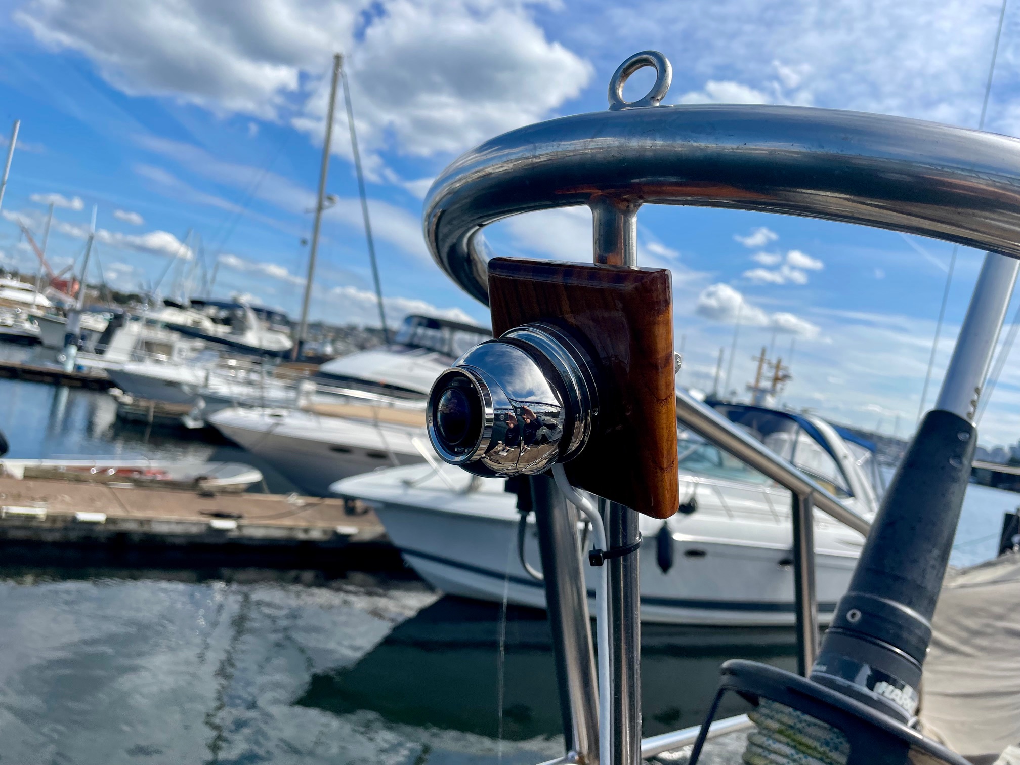
IP Cam 1
I wanted a camera with video to help keep watch since I often single hand Apropos. In open ocean sailing, going below deck for 5 minutes is no big deal, but in Puget Sound, I seldom go below deck for more than a minute unless someone else is standing watch. Last summer I tried using a GoPro camera mounted on the bowsprit. I could view the video on an iPhone or iPad, but several problems made it almost useless. The biggest issue was losing connection. The WiFi signal just wasn’t reliable from the bow to the cockpit and there was no signal when going below deck, where it would be most useful. Also, the battery life of the GoPro would only last an hour or so unless I shut it down, and powering it back up whenever I wanted to use it was time consuming. So when I started looking at new chartplotters, I discovered the SimRad IP Cam 1. Here are the main features:
- Simple setup with B&G Zeus multifunction displays
- Rugged 316 stainless steel construction designed to withstand saltwater environments
- 1920 x 1080 Resolution
- Night time and dark area operation high performance IR LEDs (10m range)
- 1.8mm wide-angle lens
- Power Over Ethernet (POE) or 12V supply options
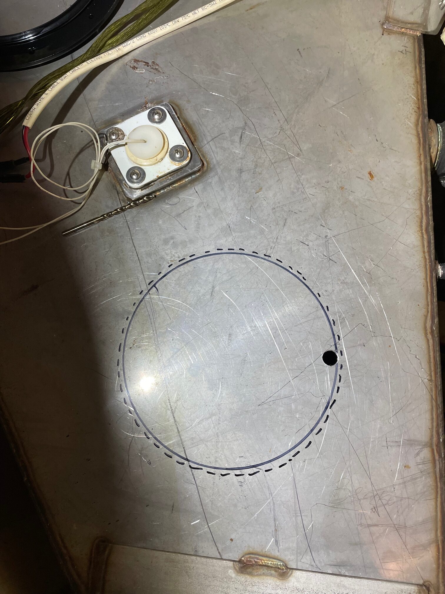
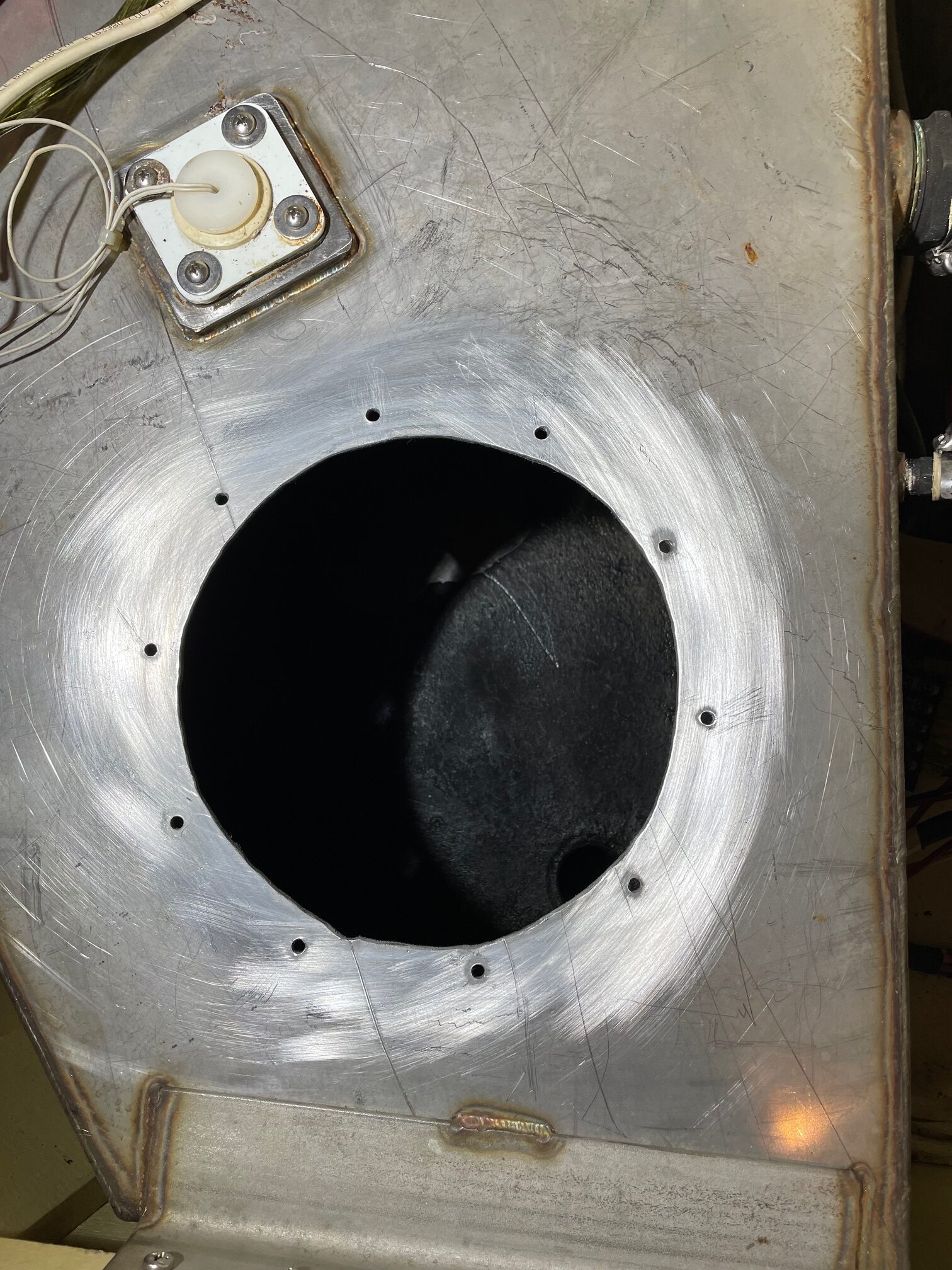
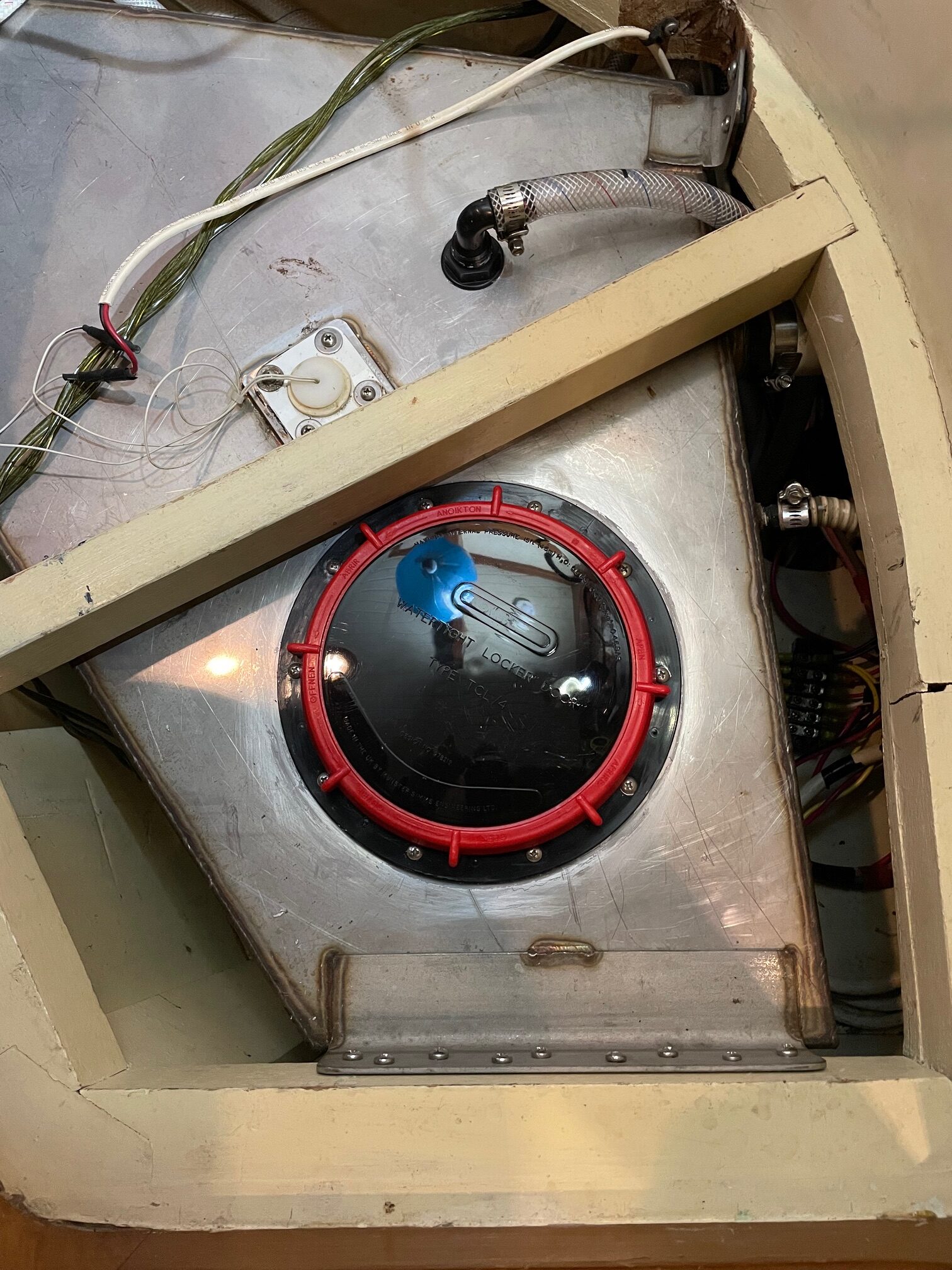
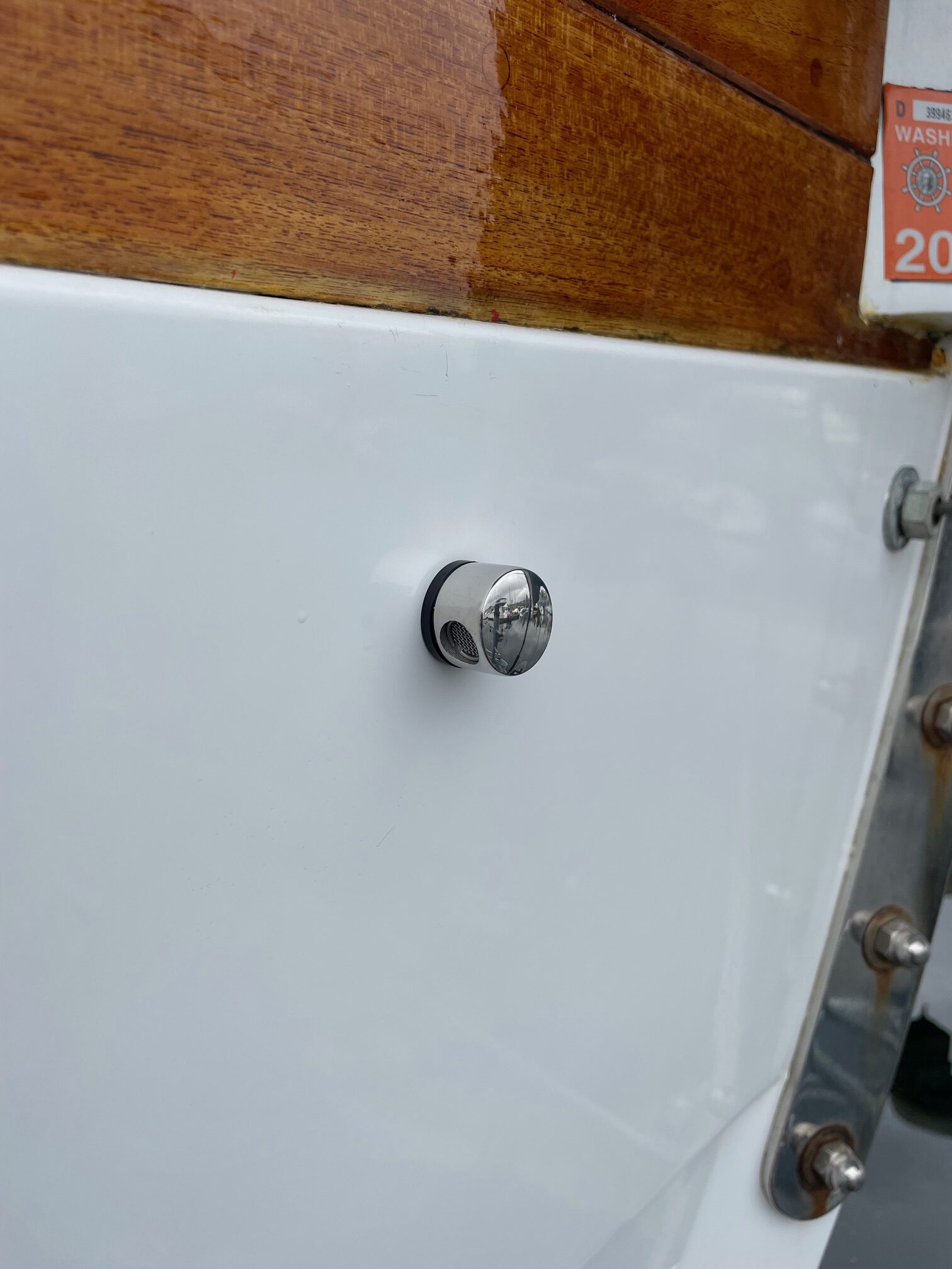
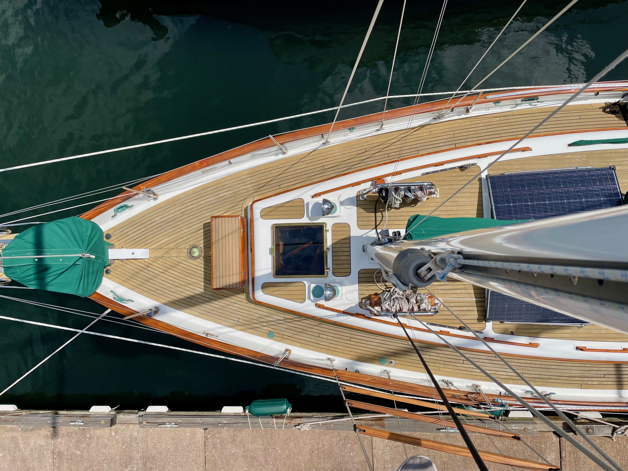
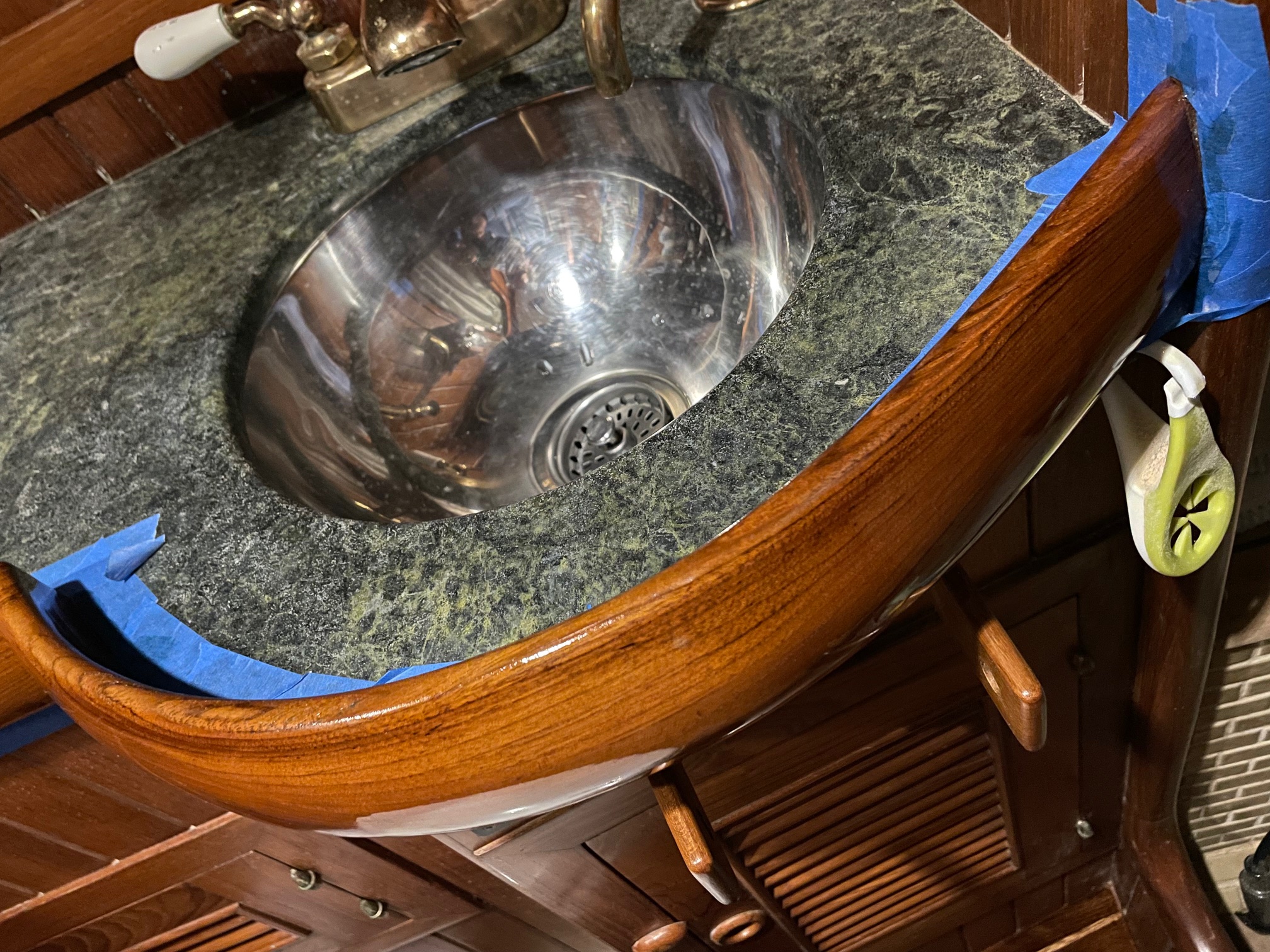
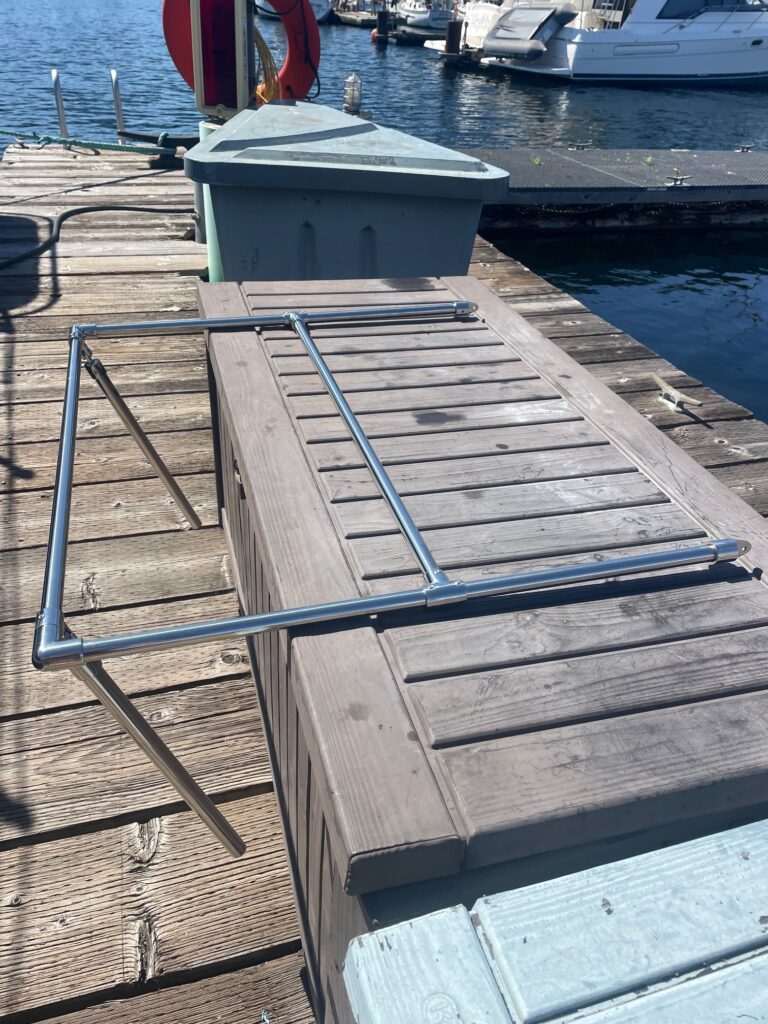
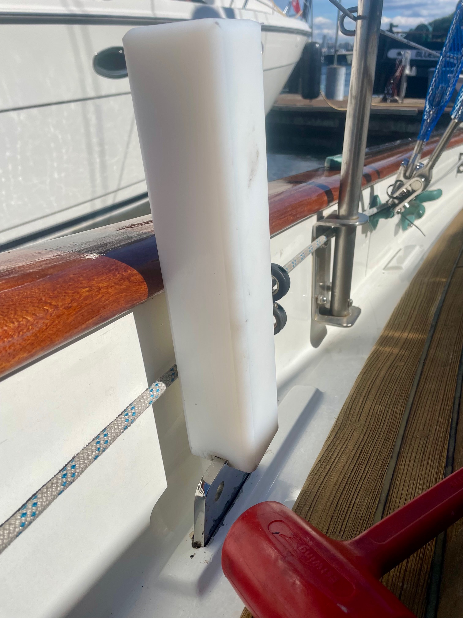
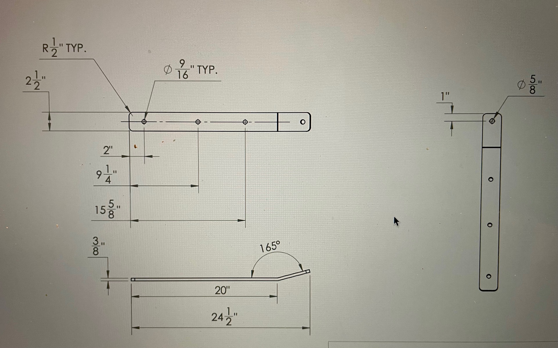
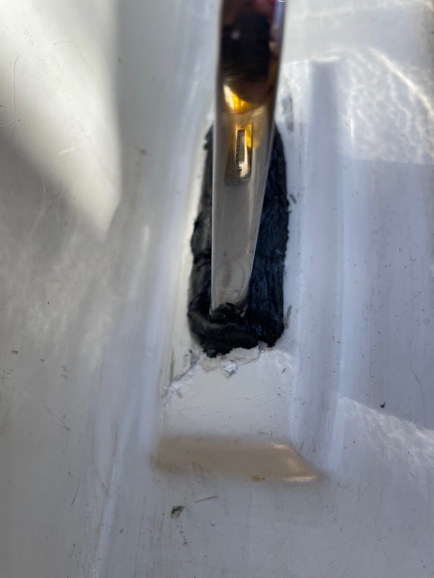
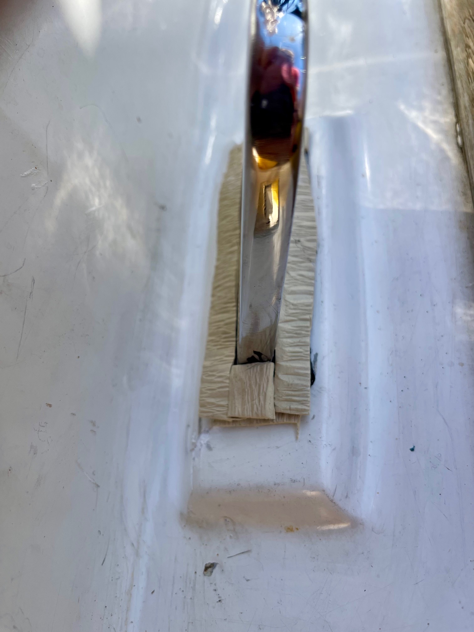
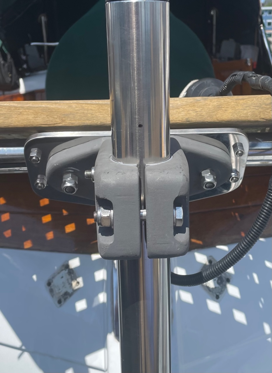
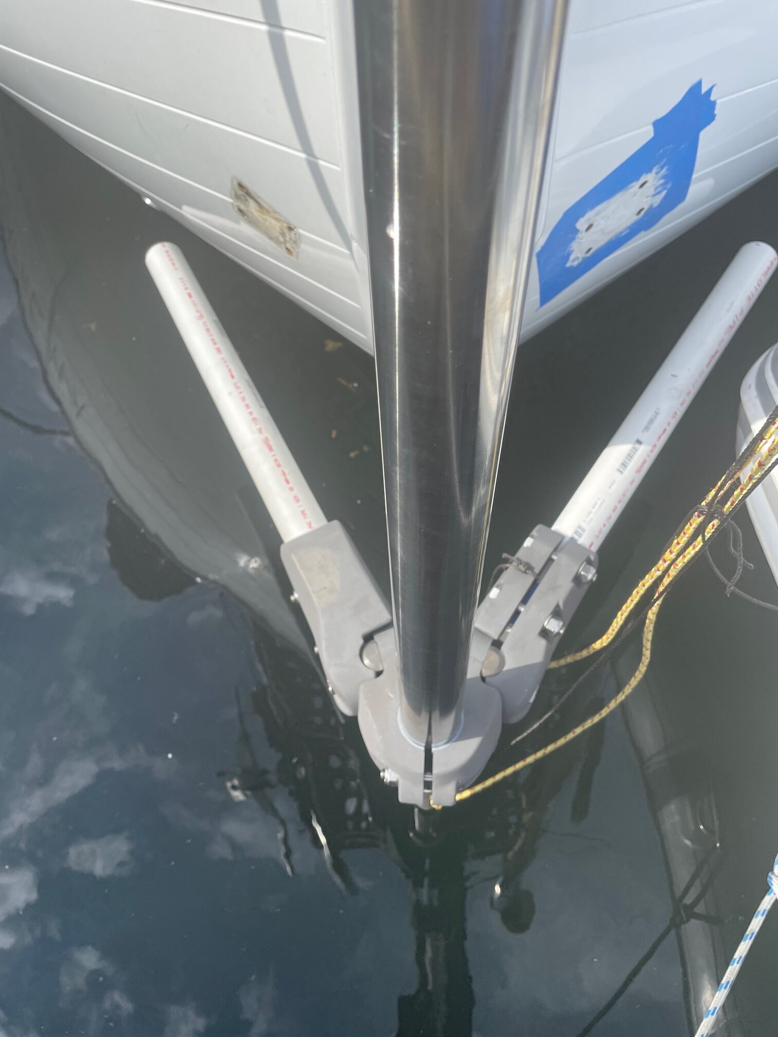
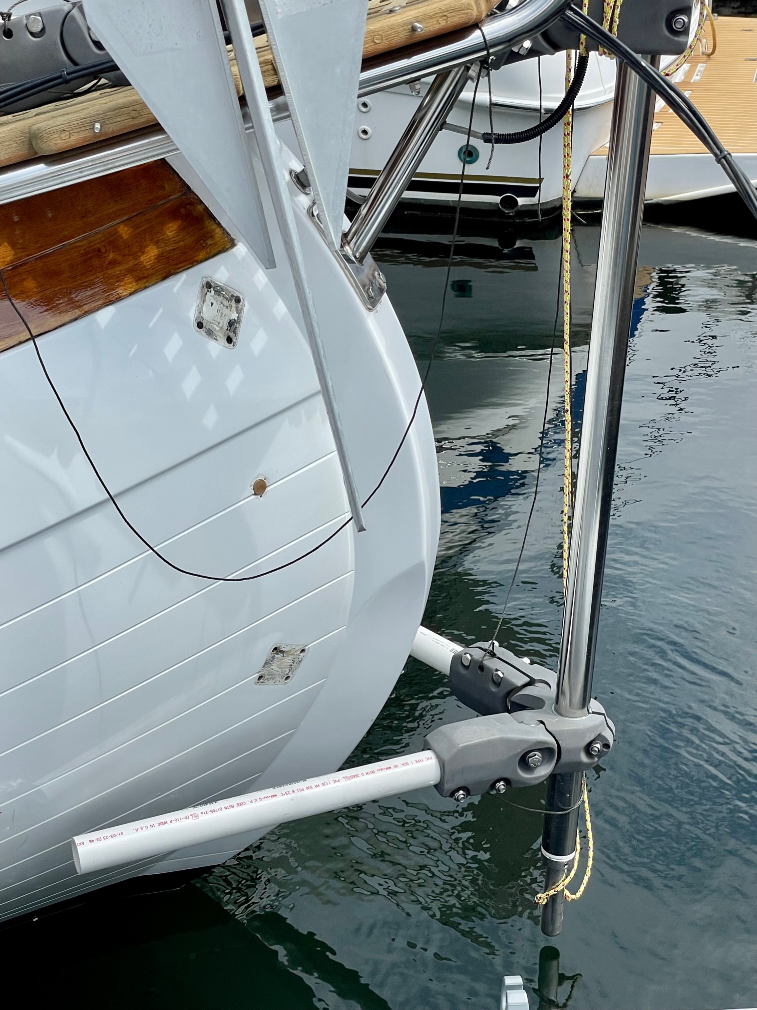
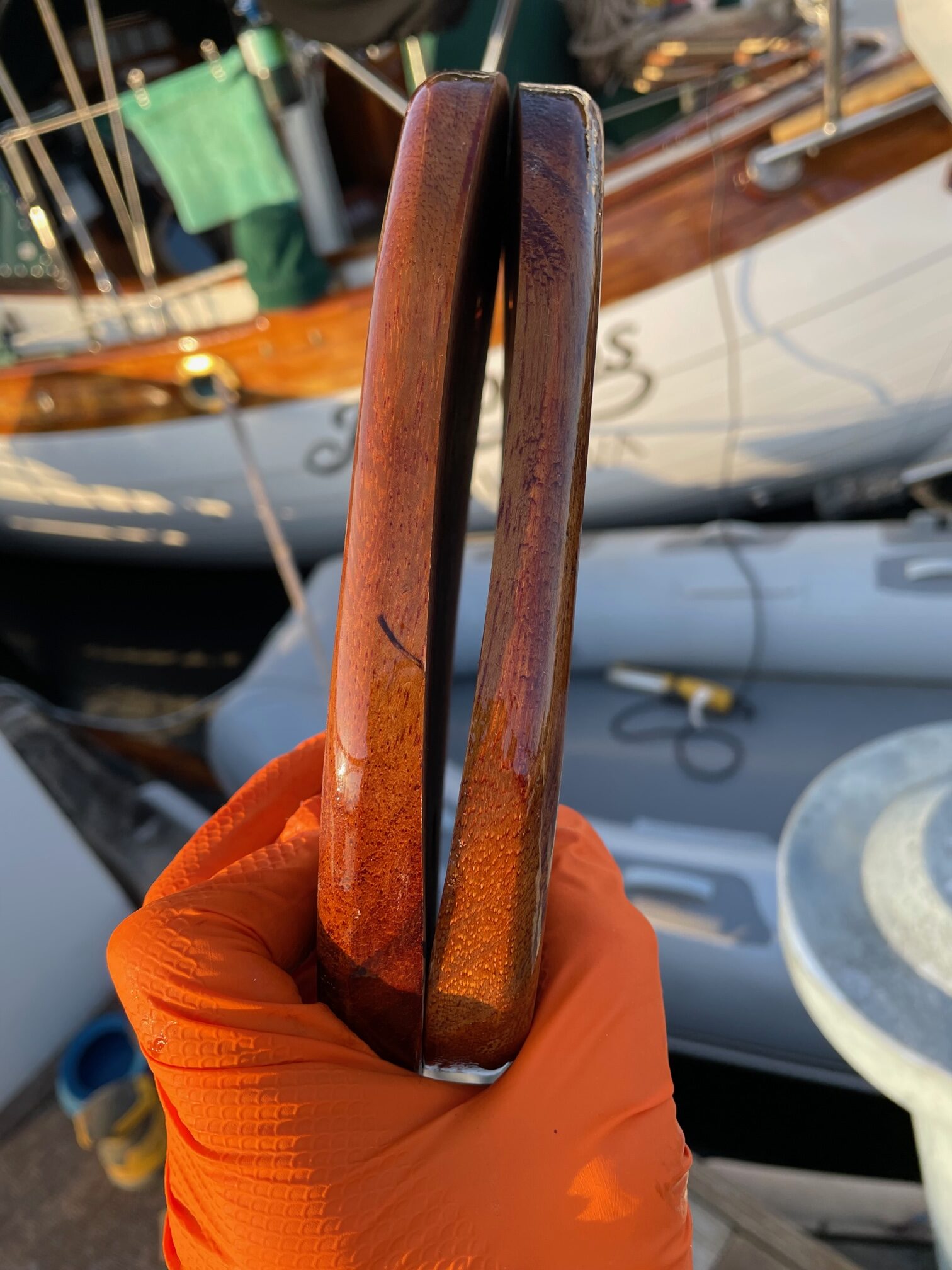
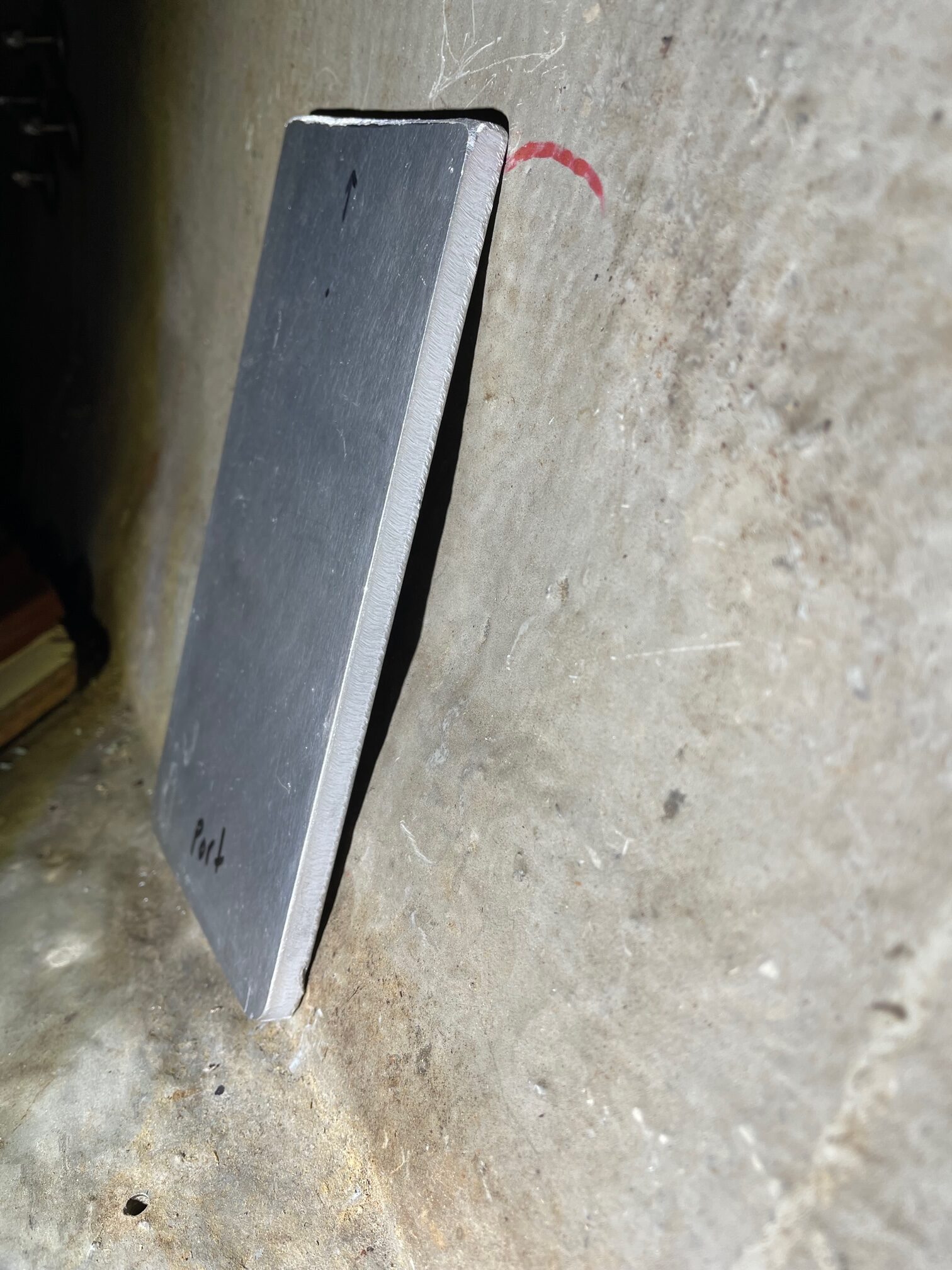
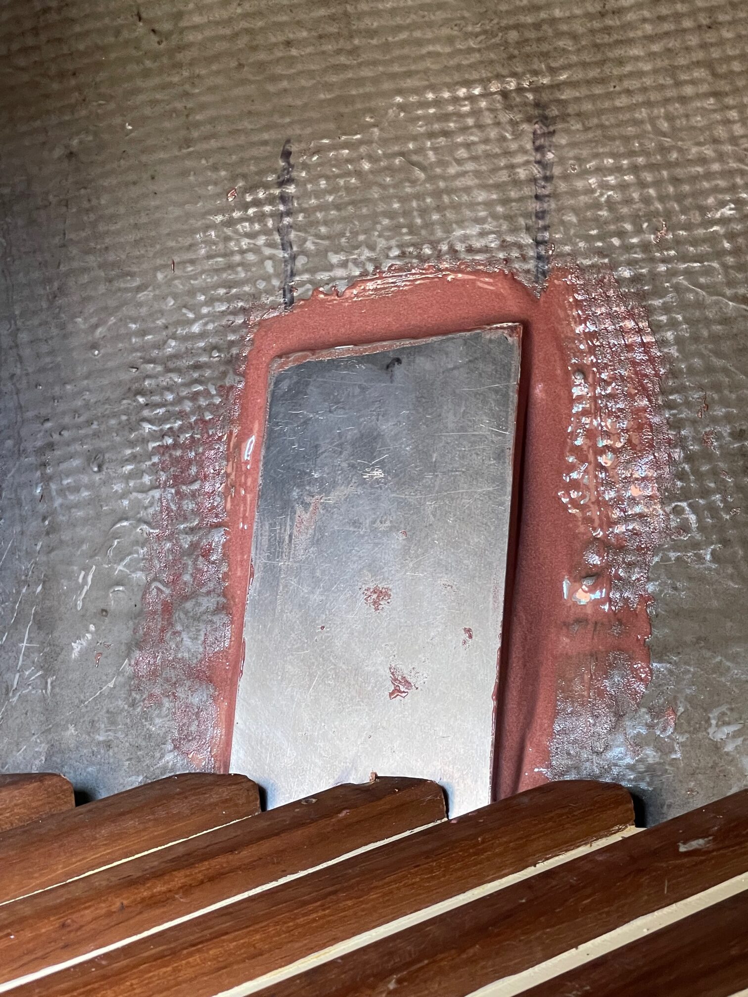
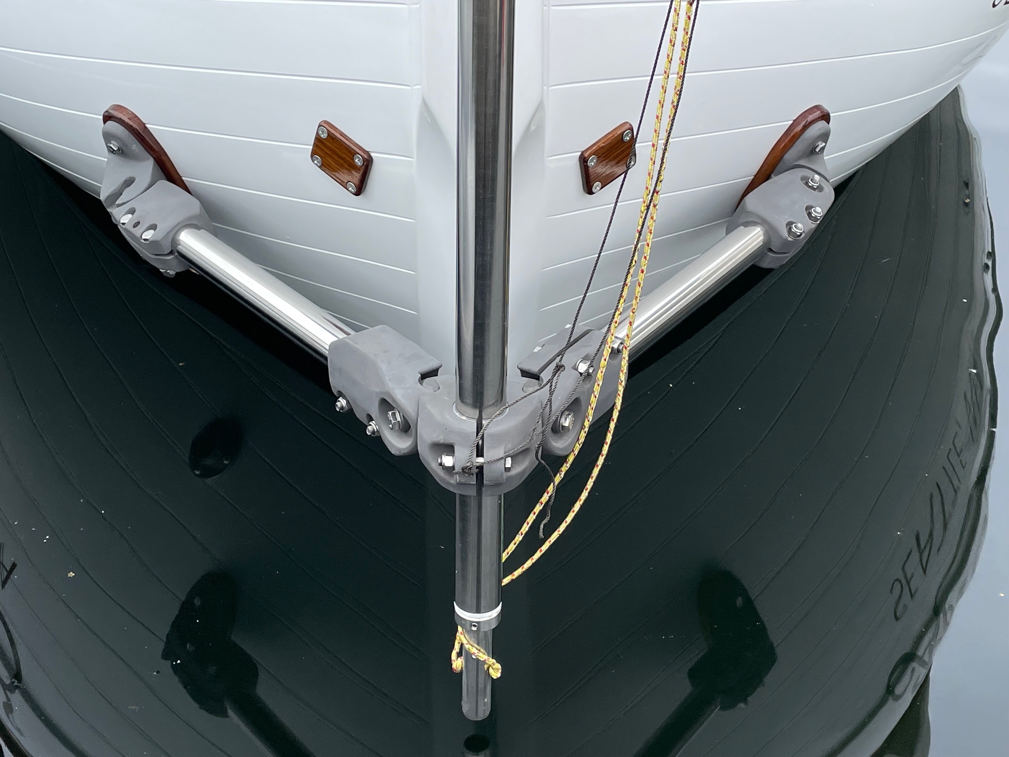
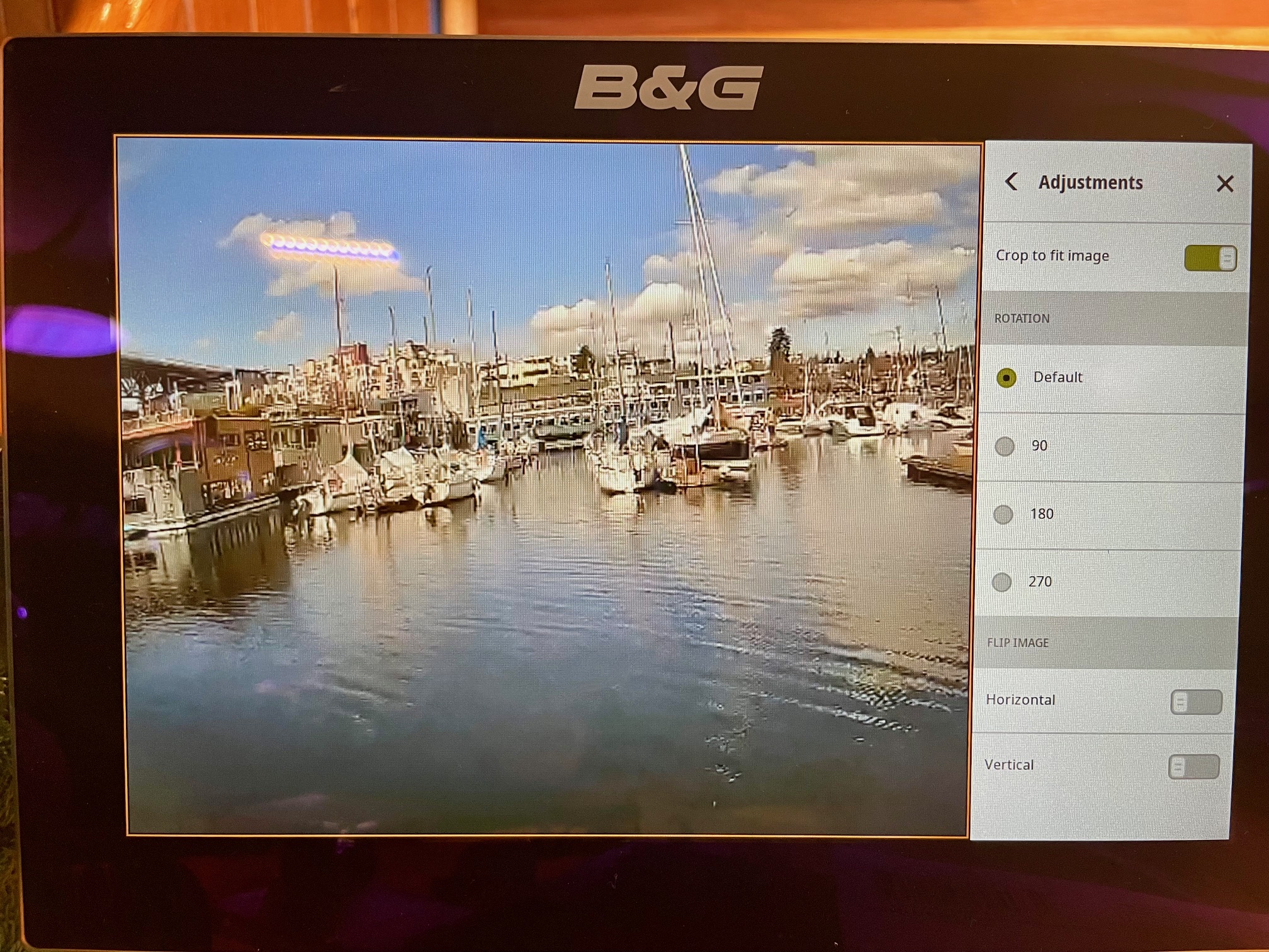
I connected it using Power Over Ethernet (POE) with a switched power connection so I could toggle it on and off from the nav station. I ran the CAT7 Ethernet cable to the bow and mounted the camera to a piece of teak, and attached it to the bow railing. I’ll see how this works and will also consider mounting another camera on the main mast around spreader height (the downside is having the view partially blocked by the headsail when sailing). To use it, I just open the App on the Zeus chartplotter and select the camera.
Misc.
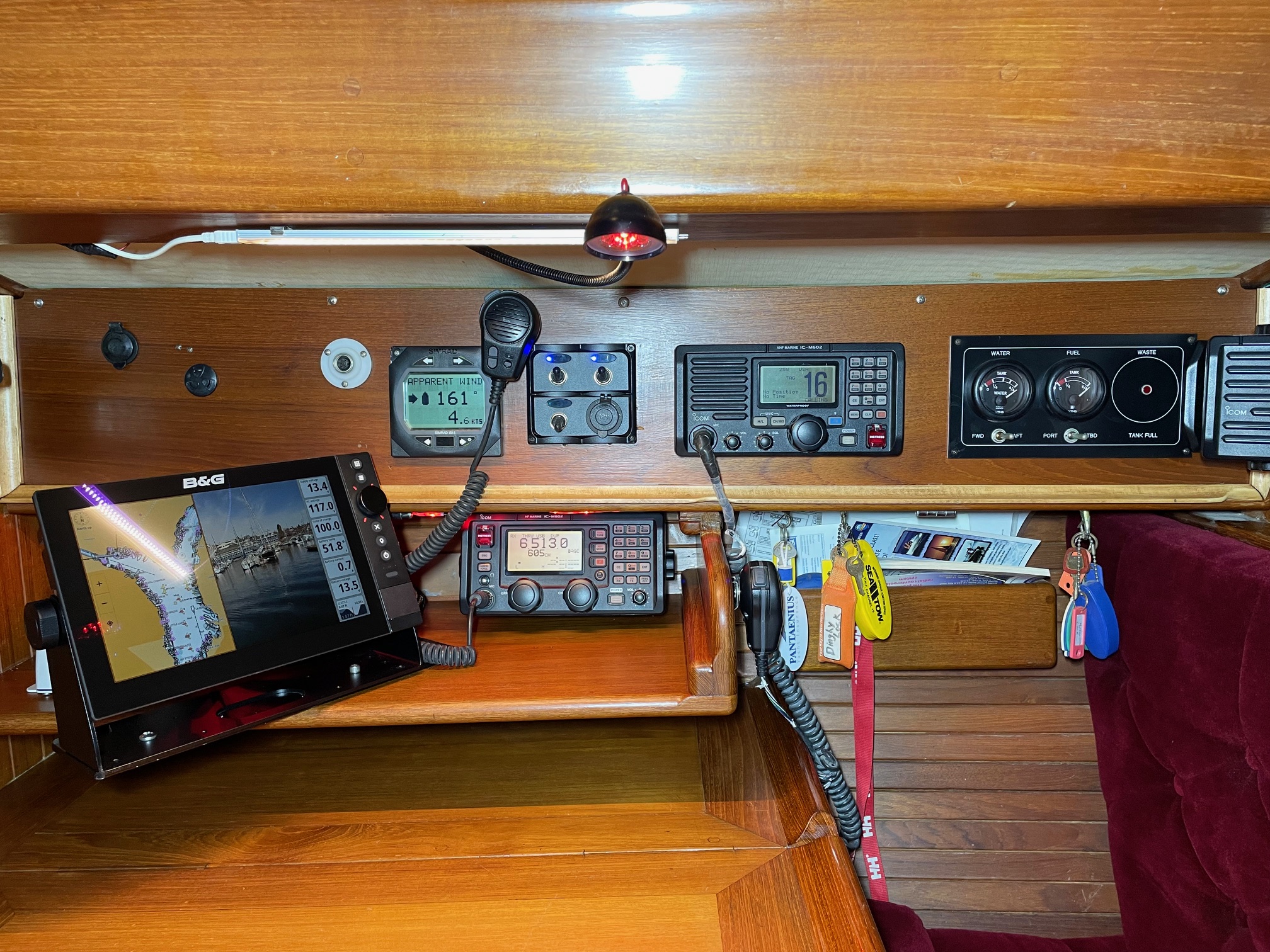
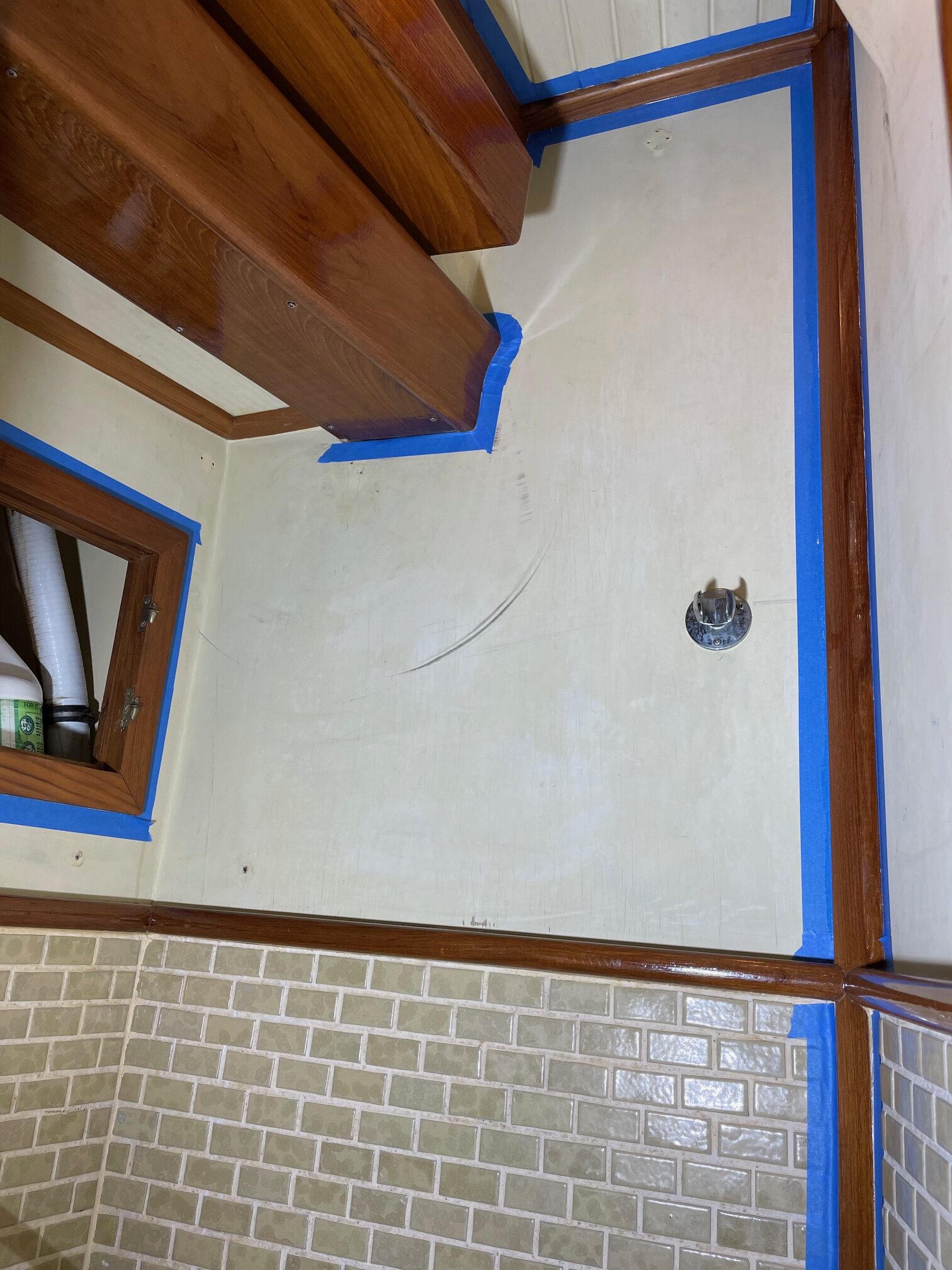
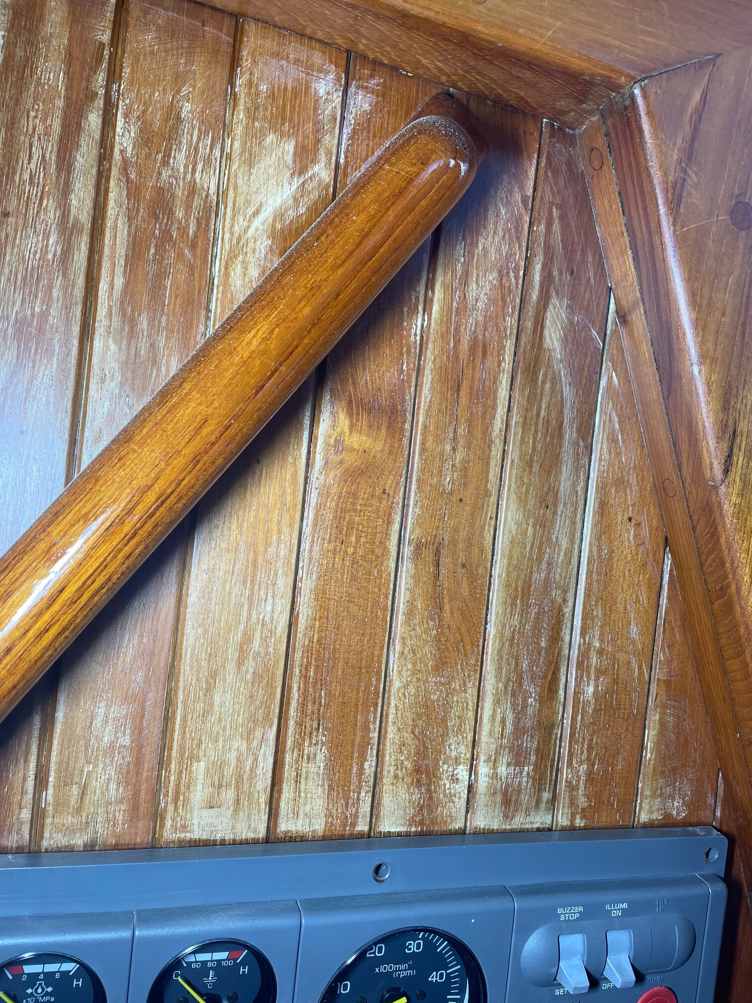
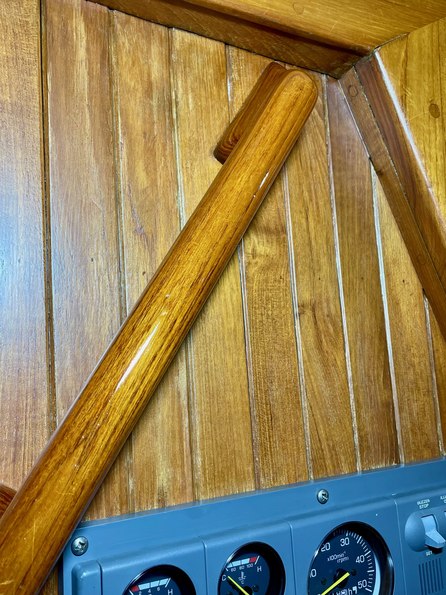
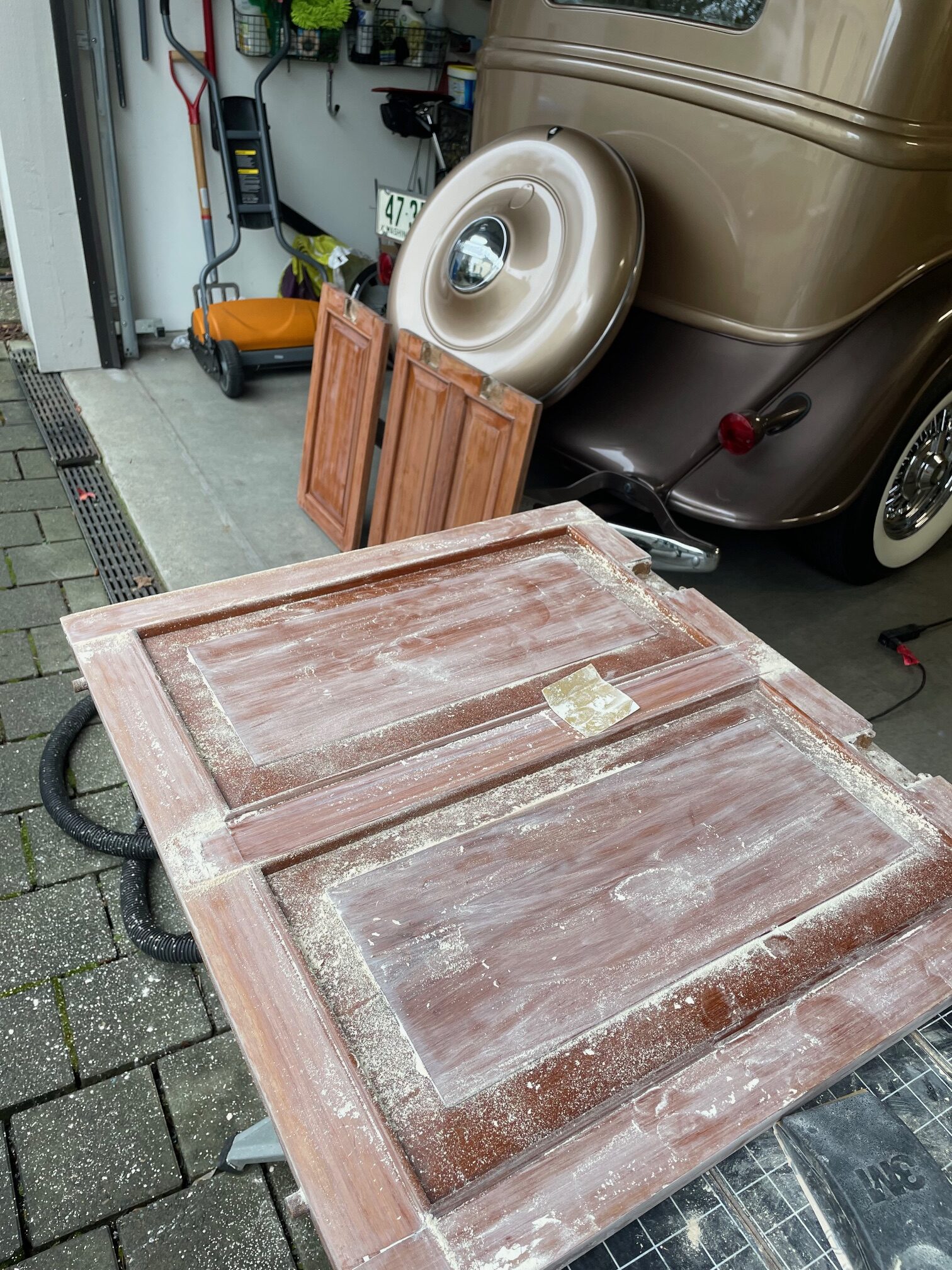
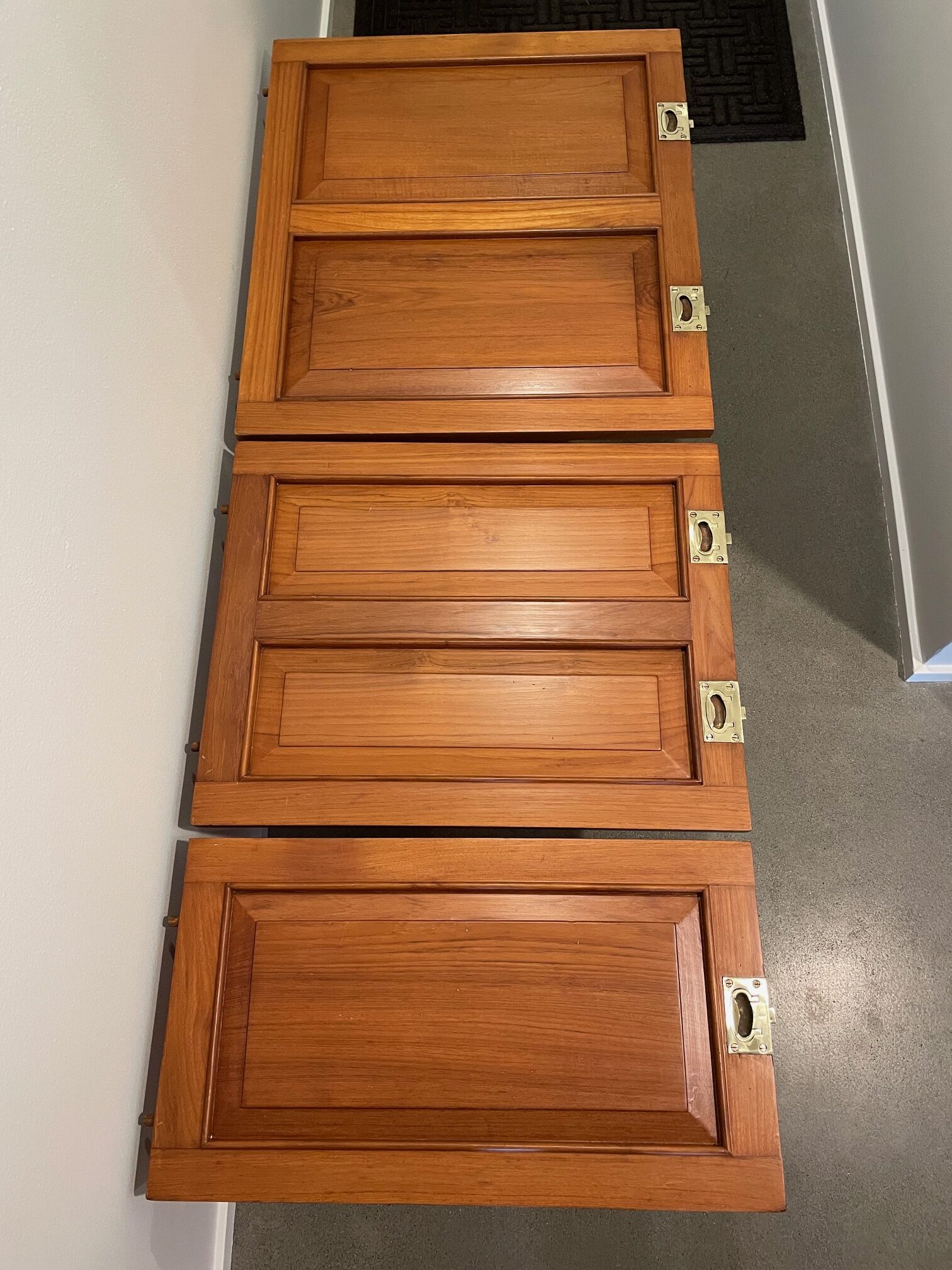
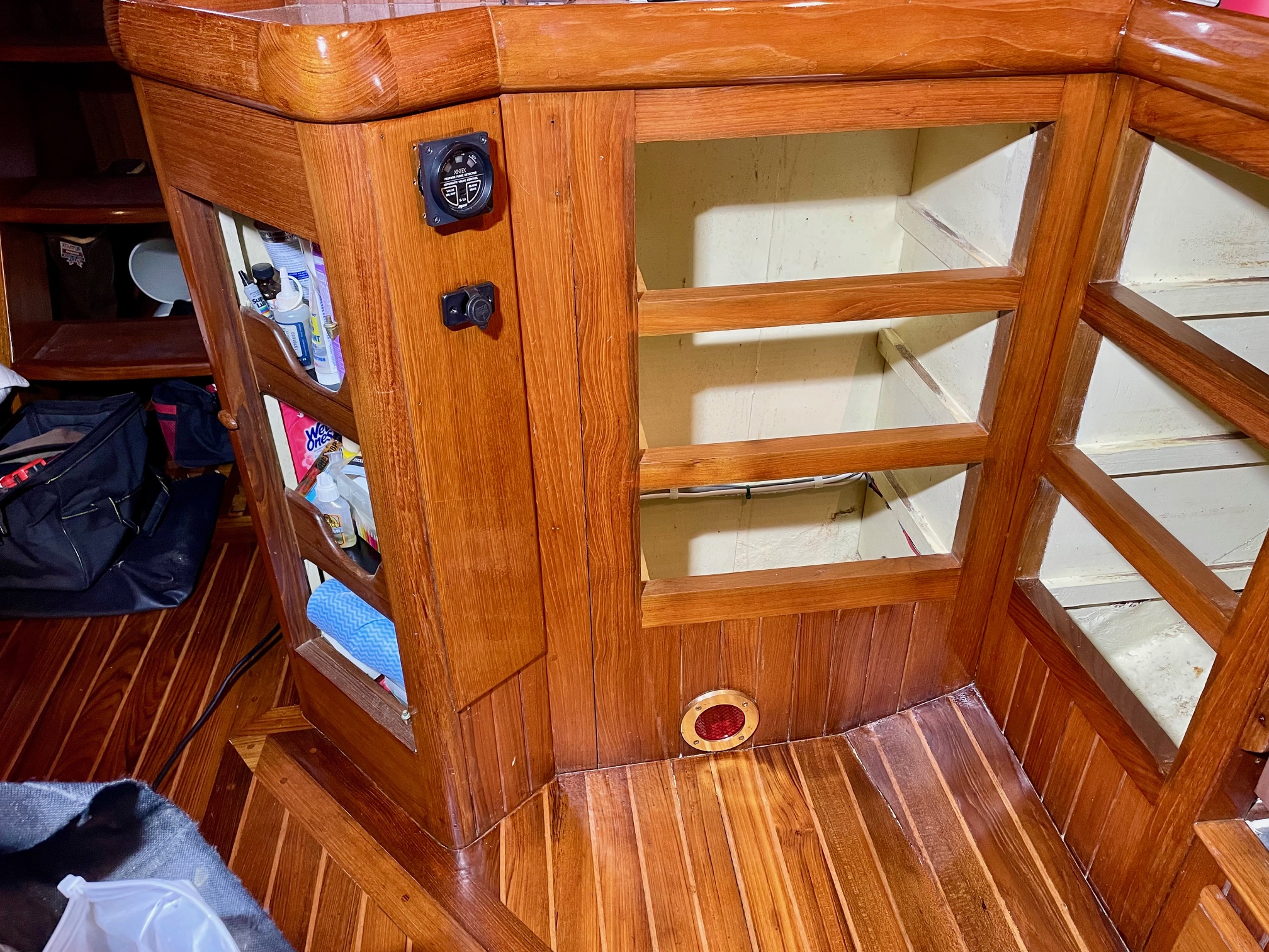
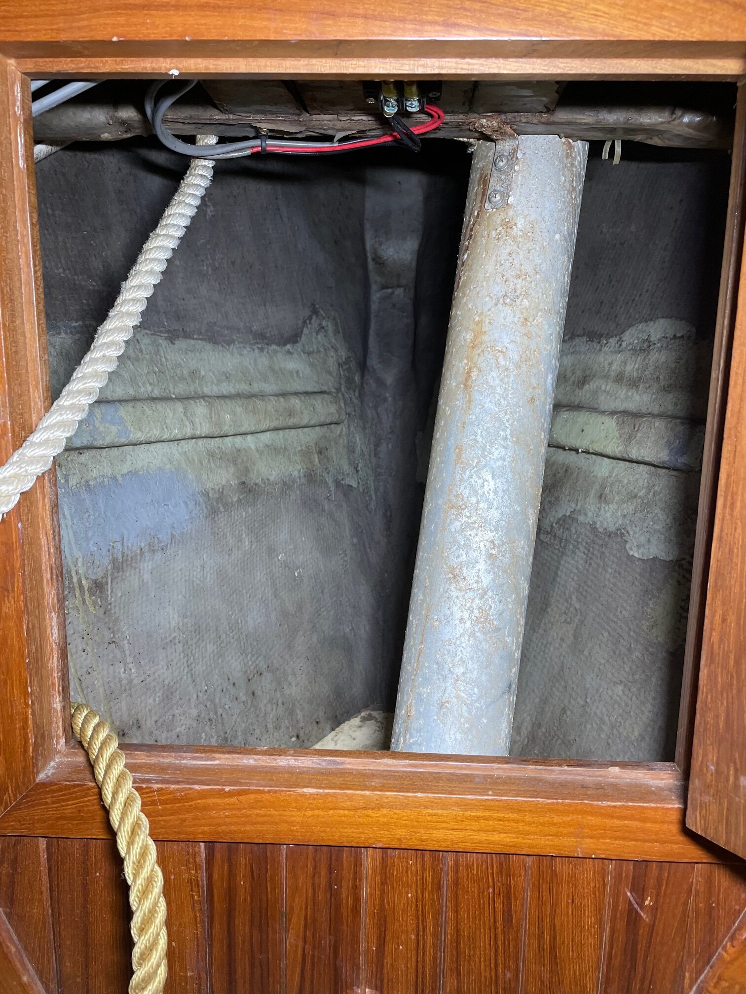
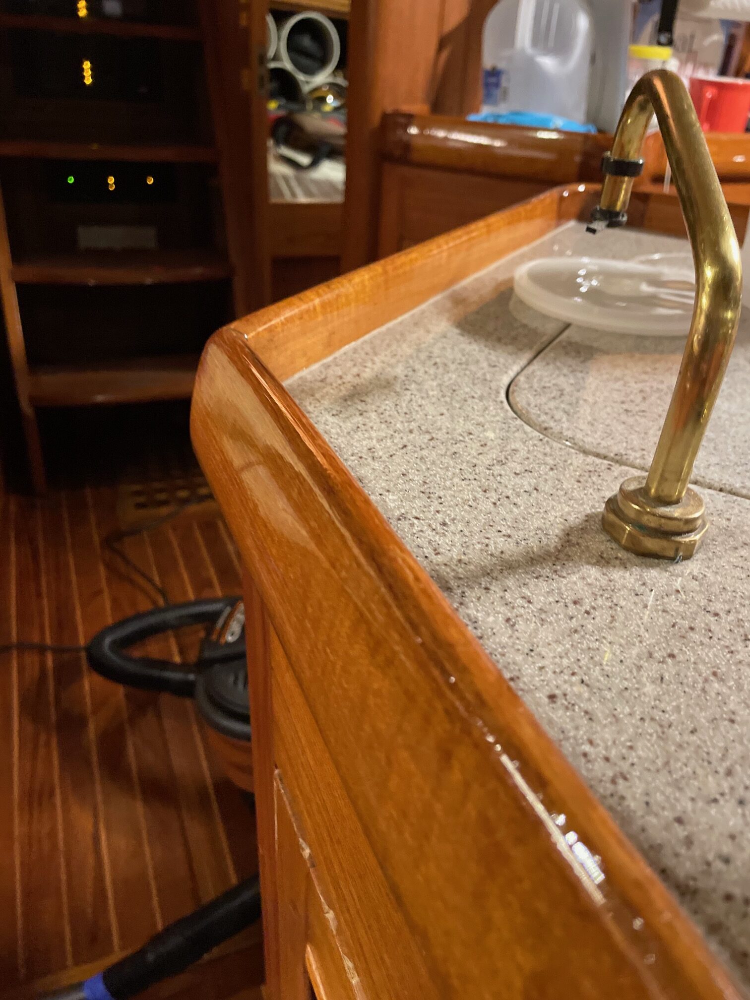
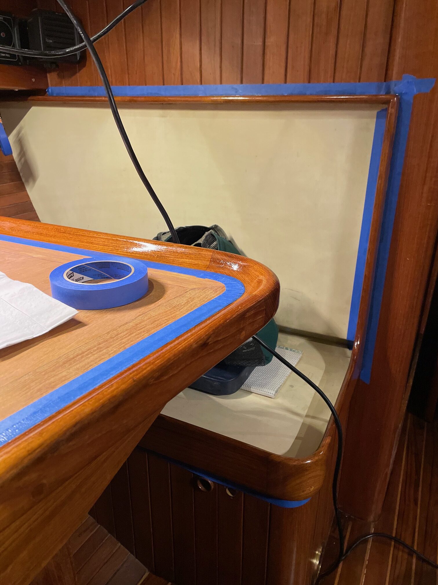
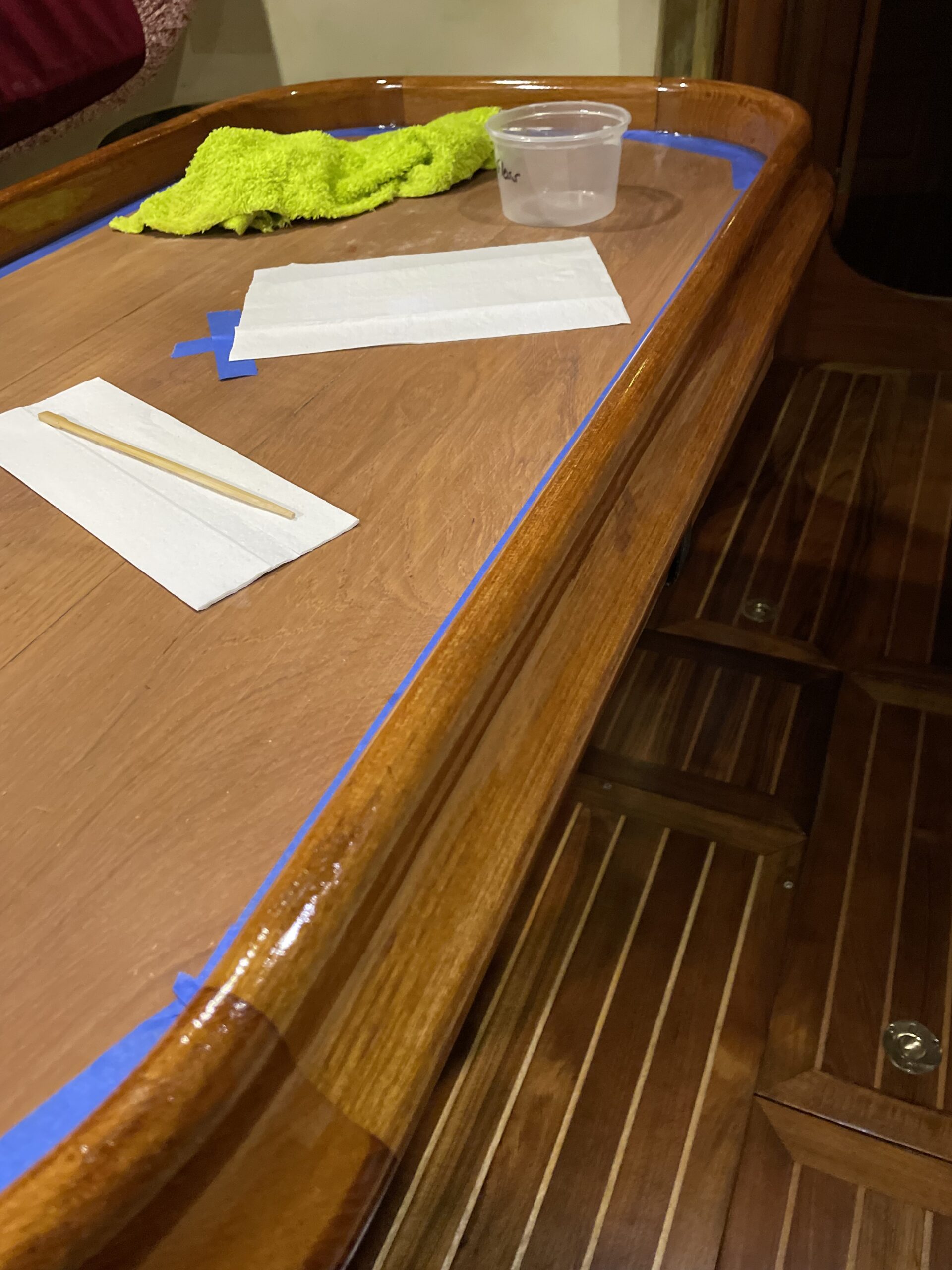
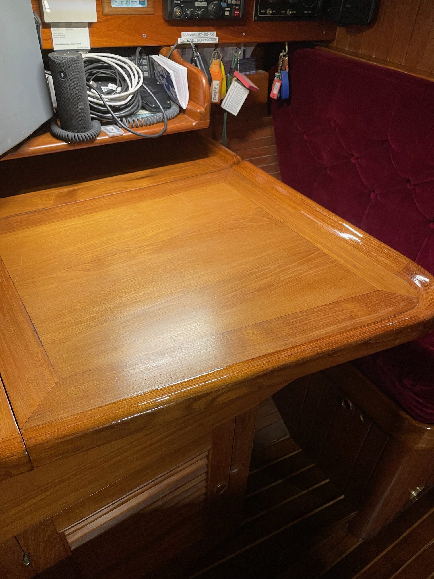
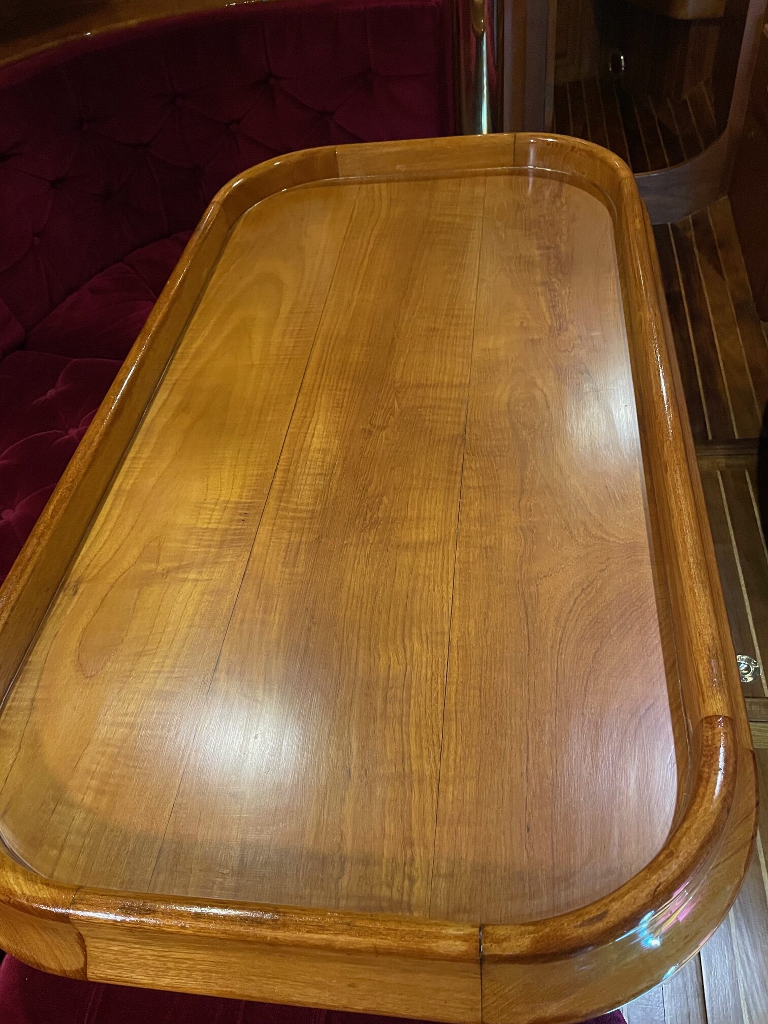
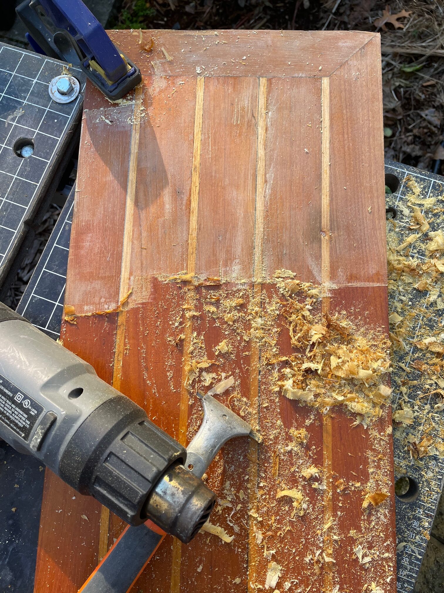
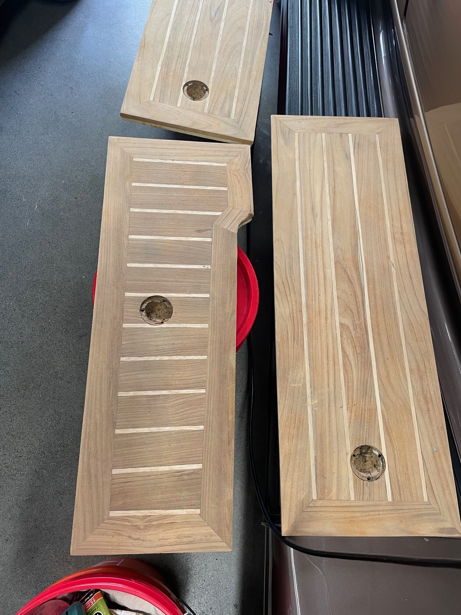
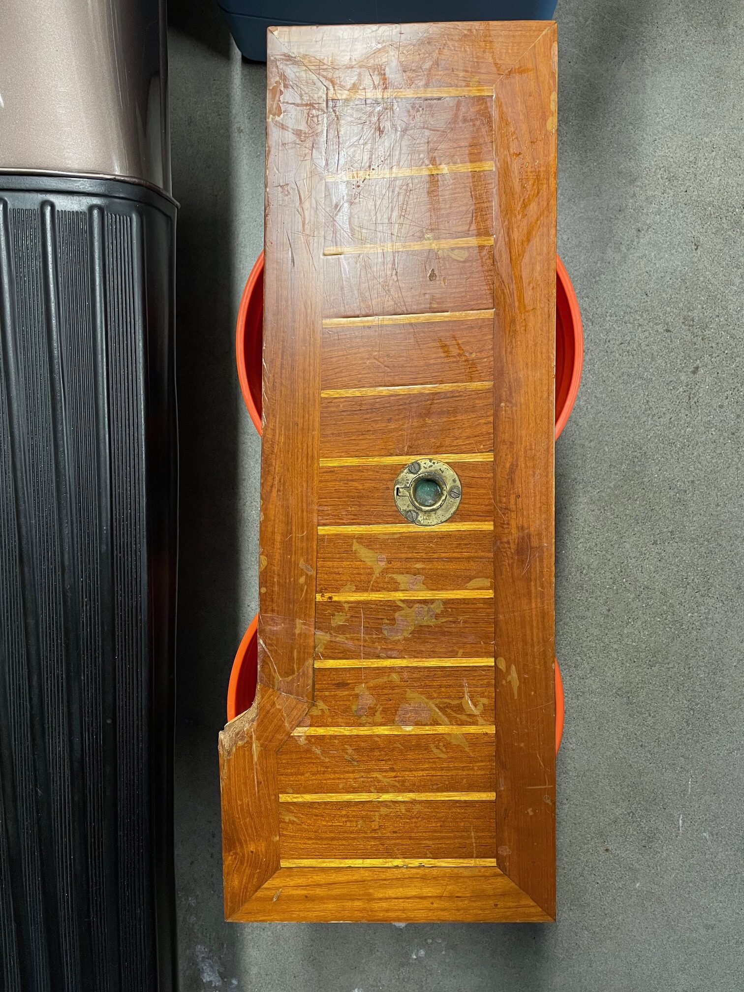
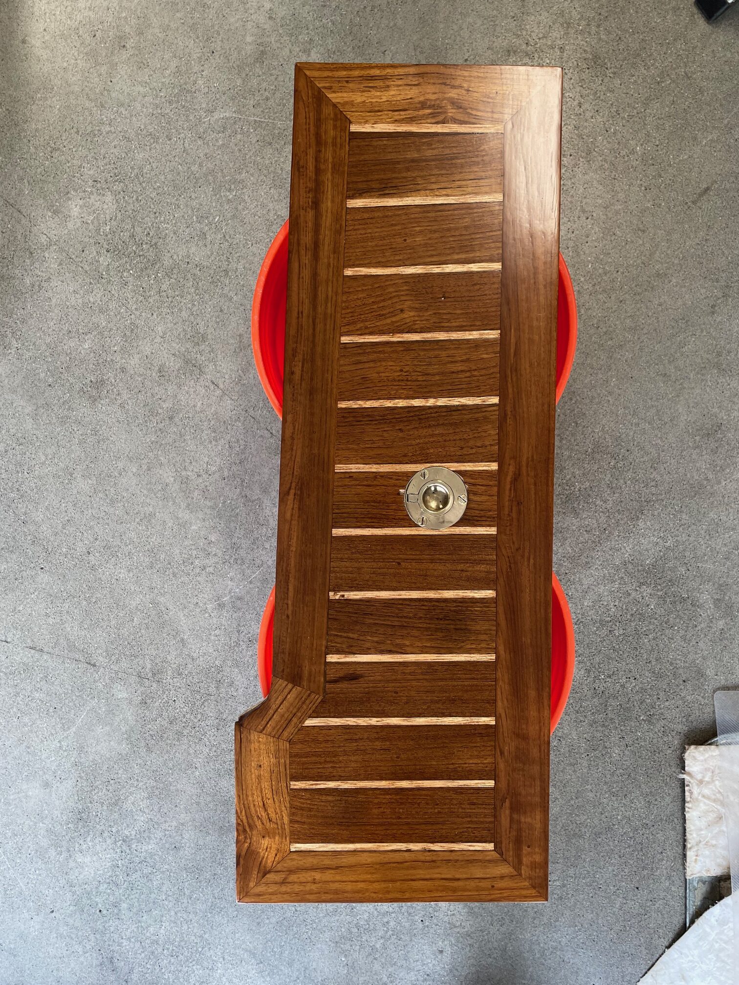
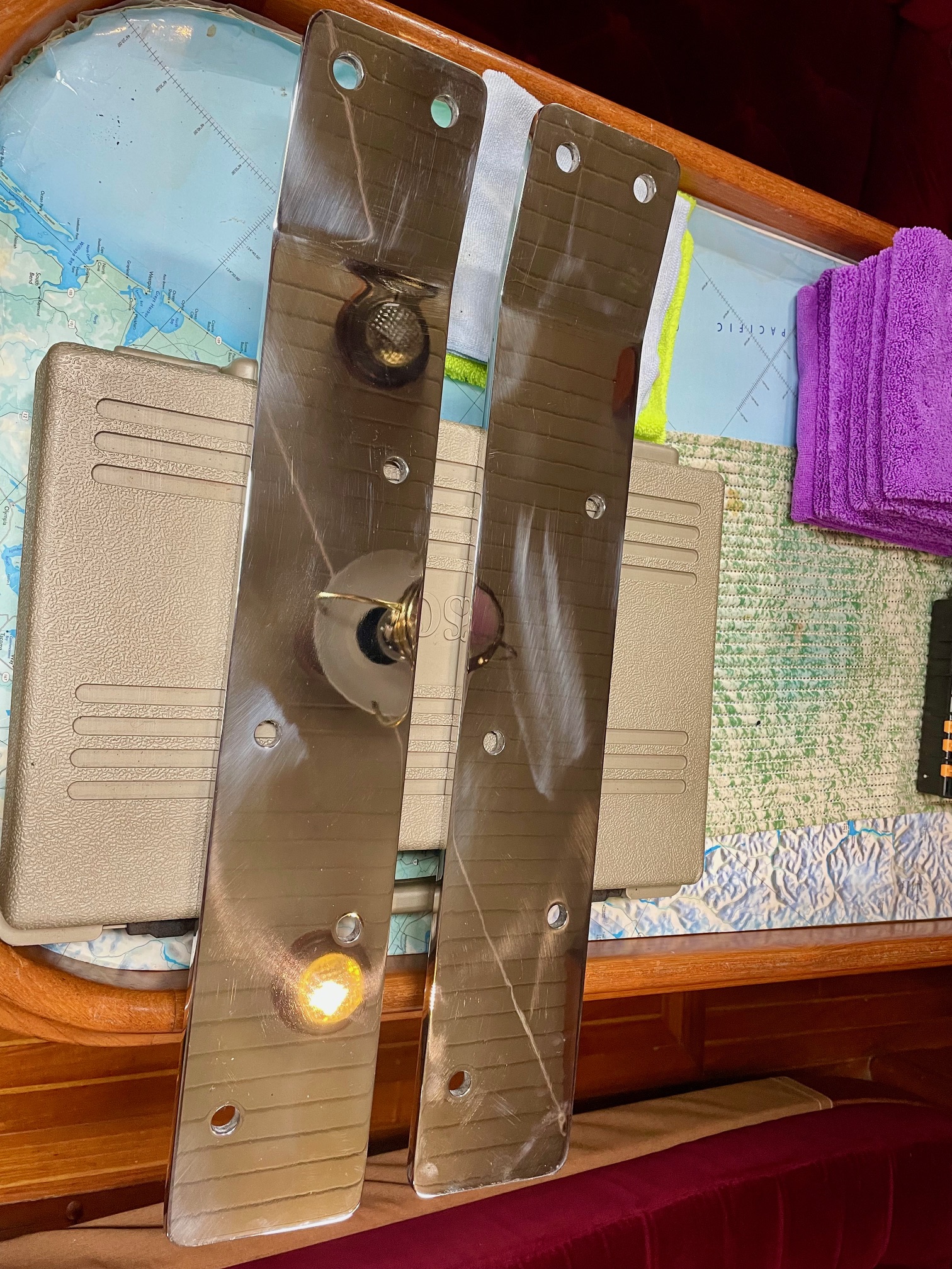
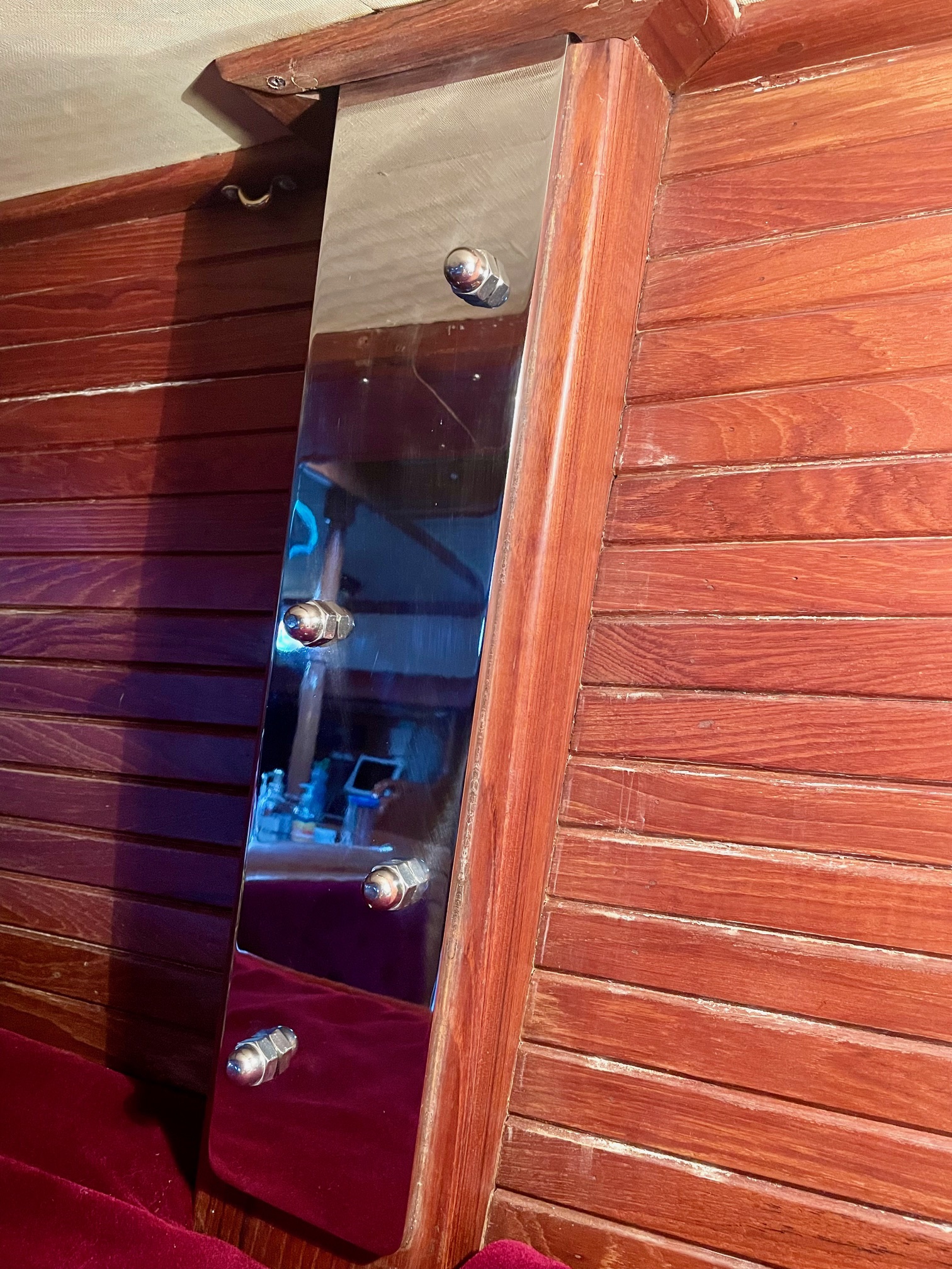
Something additional I did was to make access to the navigation station wiring bay easier. Previously, I had to undo 10 screws then pull out the panel that has equipment mounted on it and lots of wiring behind it. This made working on the panel and the wiring behind it difficult because there was nothing to support the panel. So to make it easier, I added hinges along the bottom of the panel to allow it to pivot down to expose the back of the equipment and the wiring behind it. The top is now fastened by just 5 screws. I hid the unused screw holes along the bottom with teak plugs and added wood trim around the outside edges to make it look better. I moved things around the panel and added an audible alarm (tied into the chartplotter for when the radar finds a dangerous target), added 3 switches–one for turning on the IP camera, one for turning on accent lighting, and one currently unused, added another DC outlet for USB charging, and refinished the panel with 4 coats of satin varnish. I also did a major clean-up of the wiring and added labels.
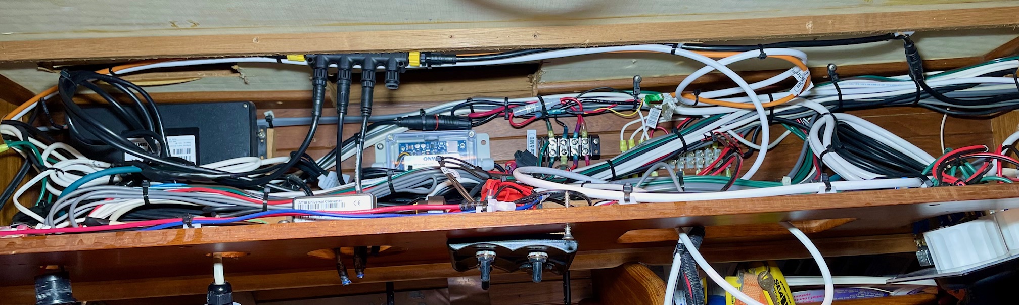
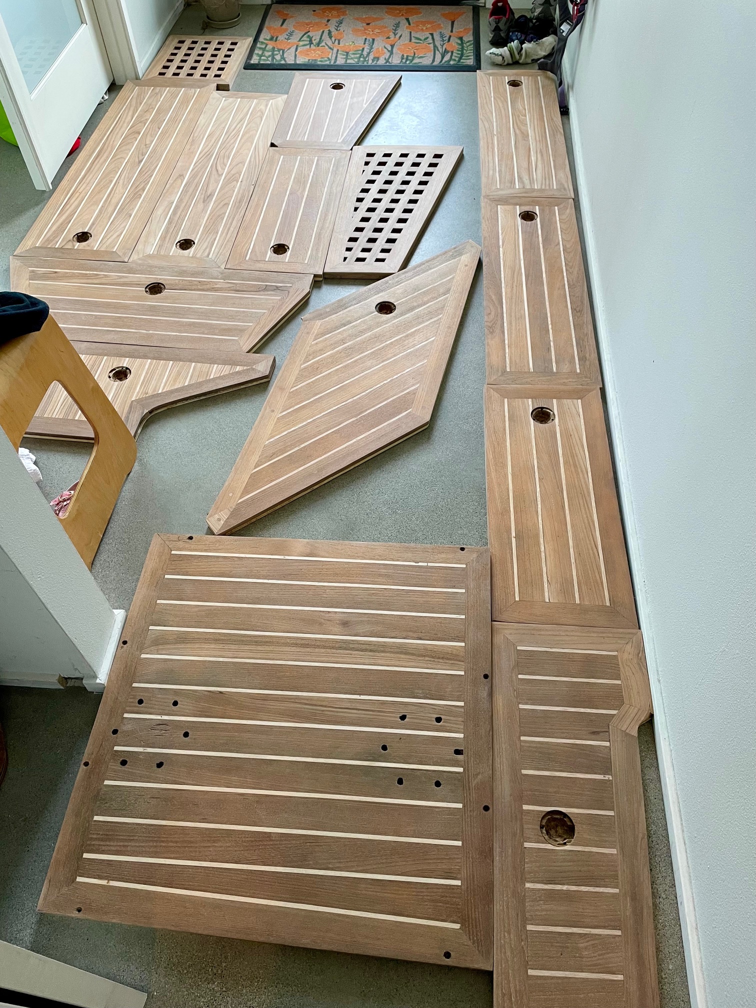
It took about a full month working full time to create the N2K backbone, remove the old equipment and wiring, install the new equipment, and tidy up all the wiring.
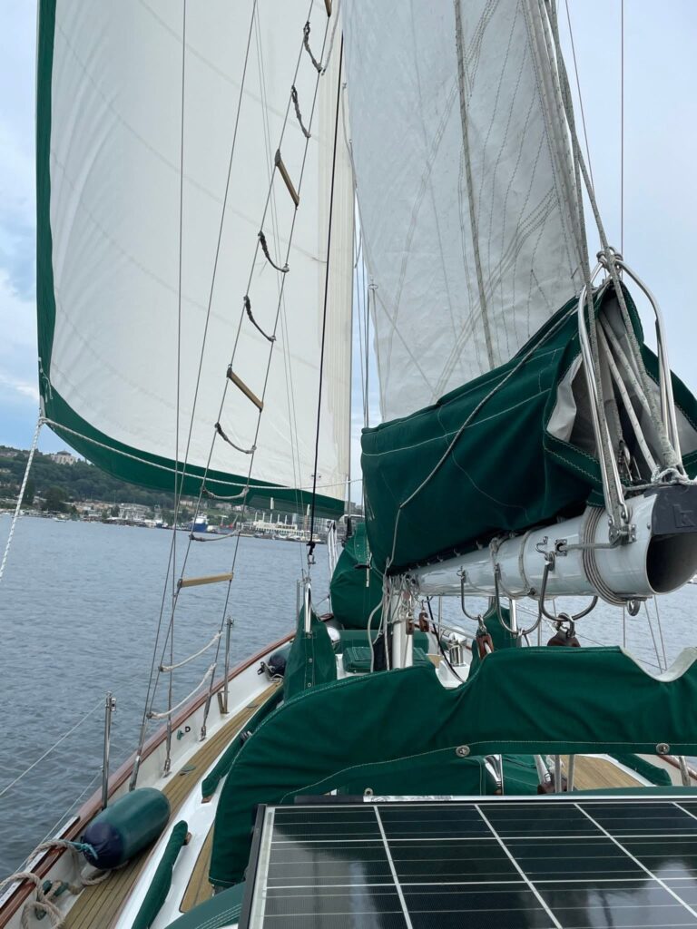
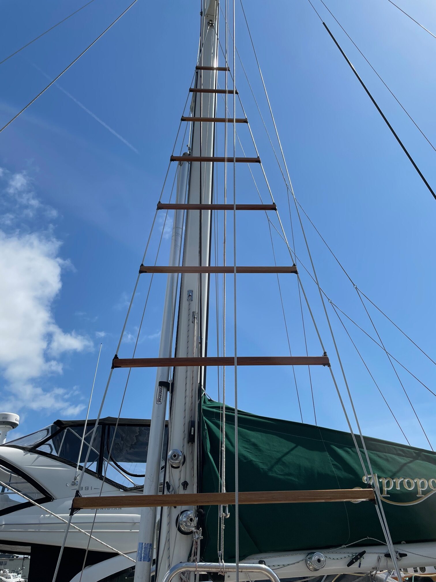
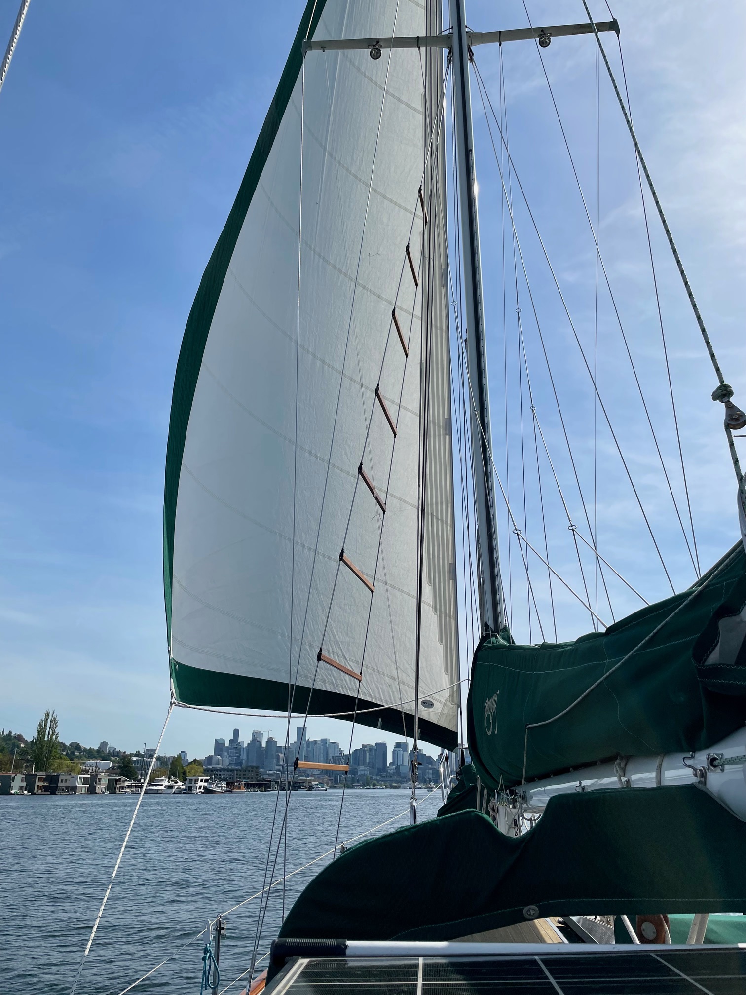
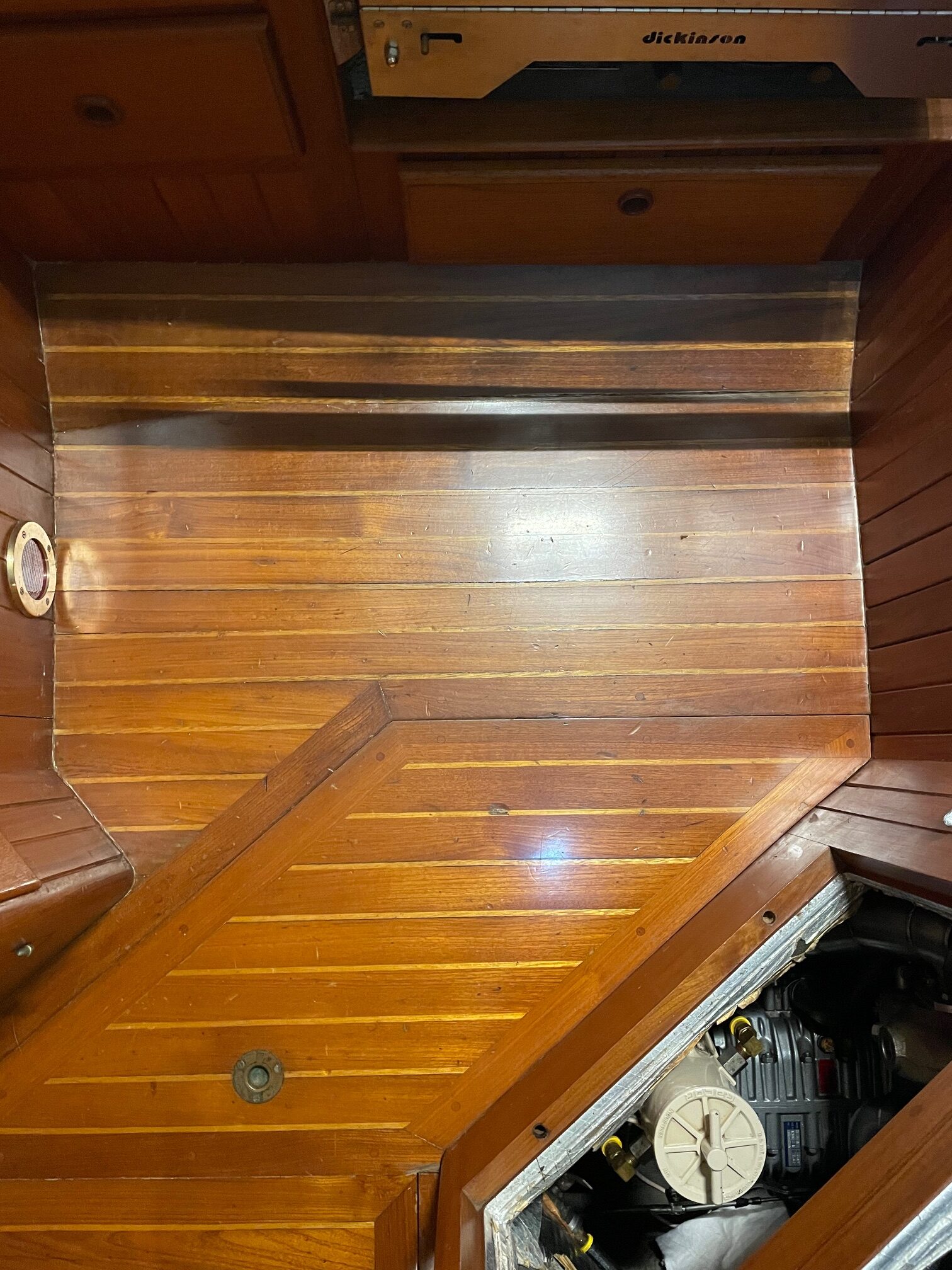
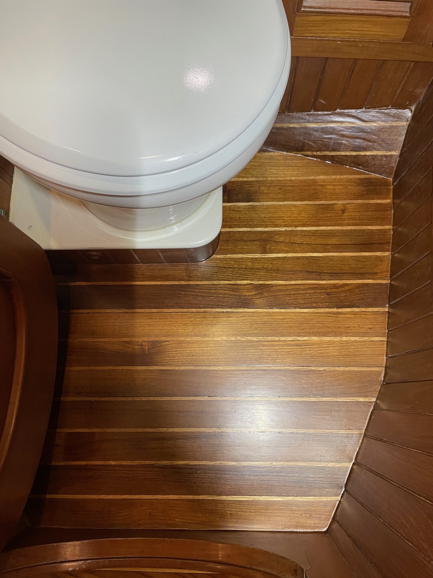
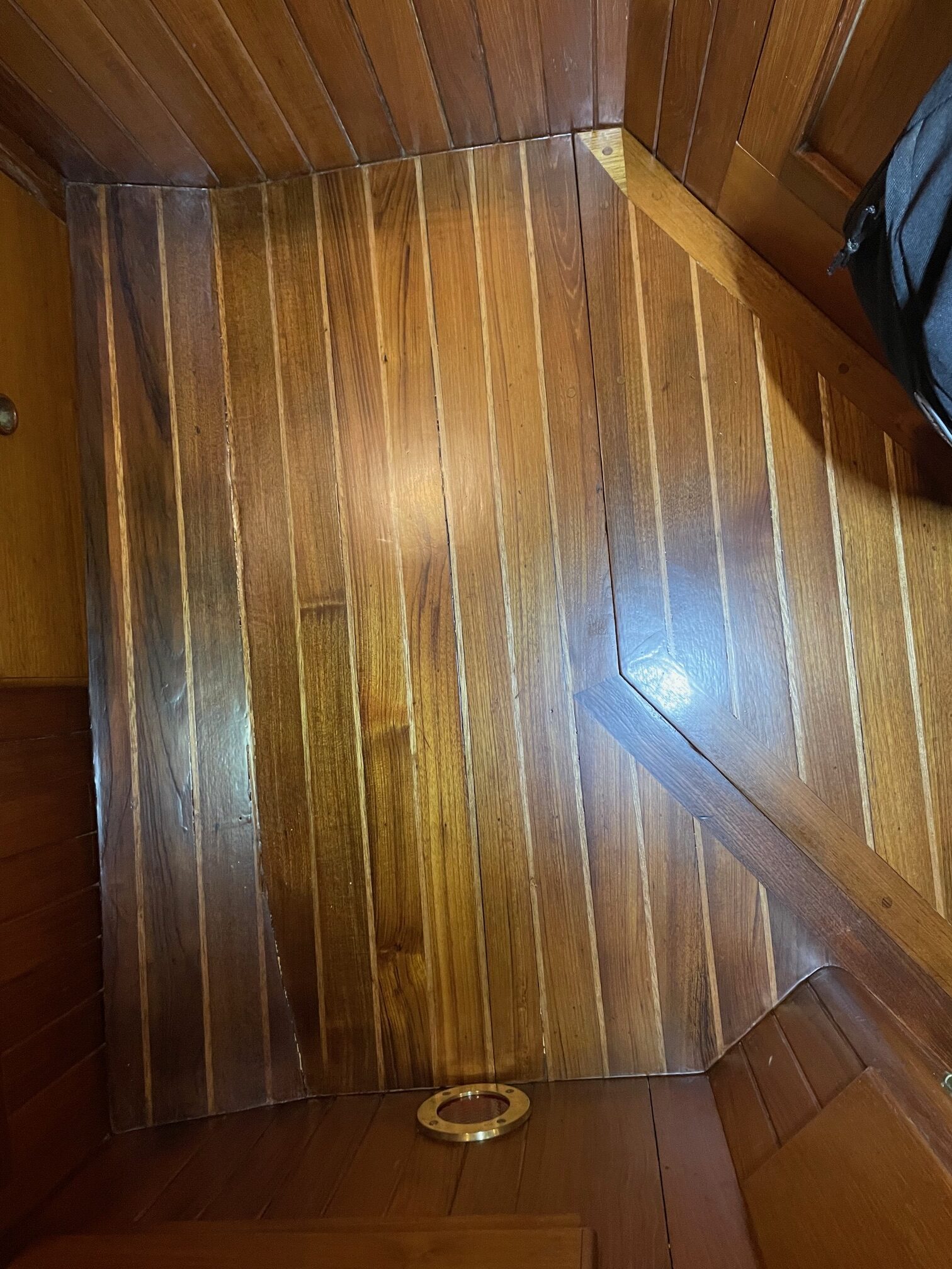
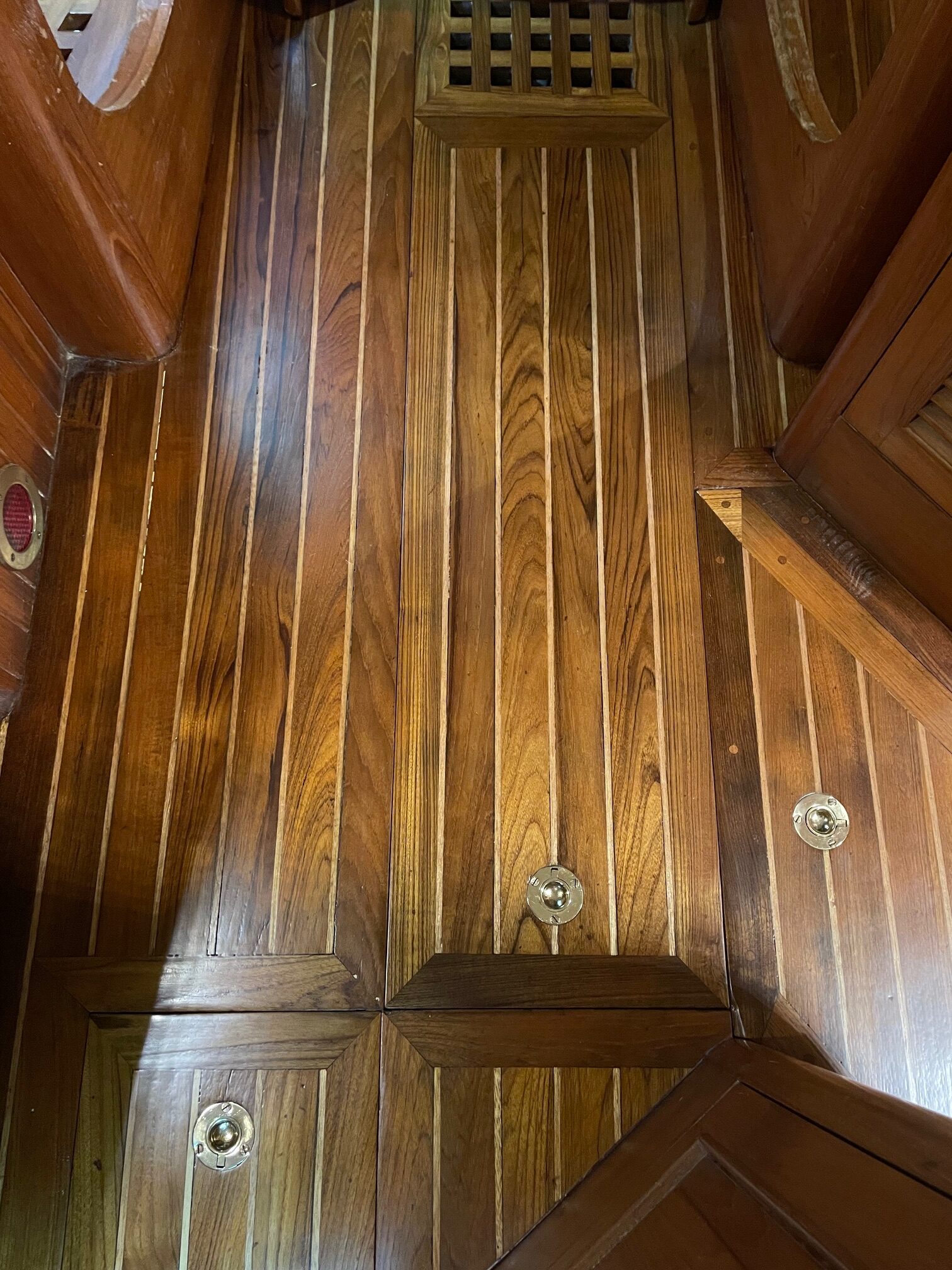
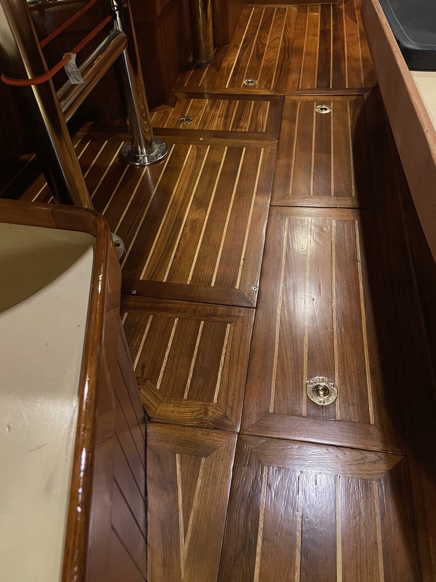
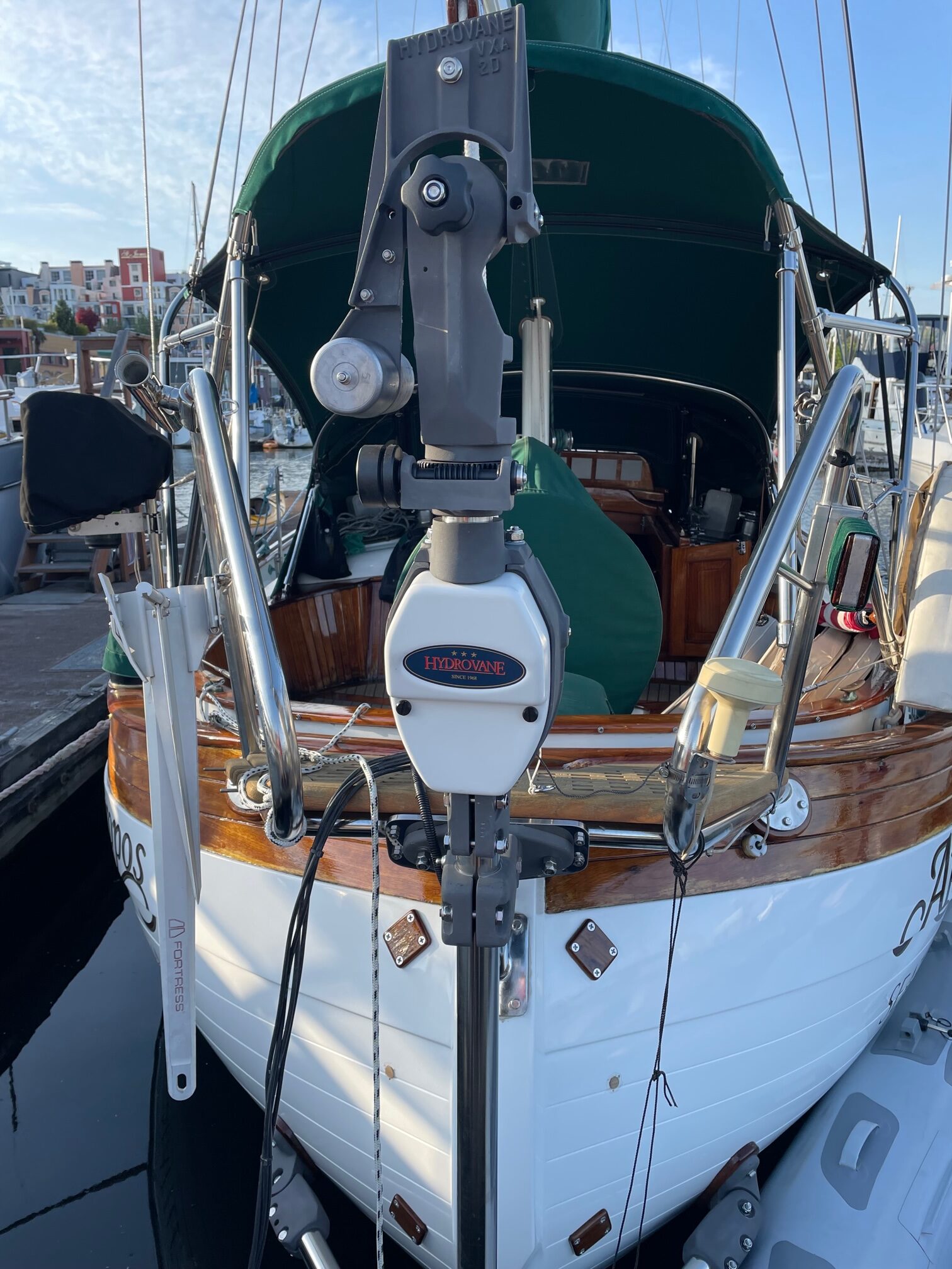
Here are some pictures of the completed work.