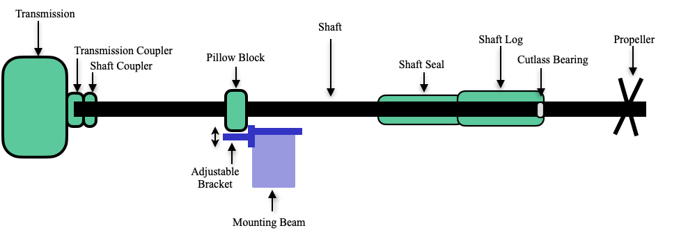
During a routine haulout in April to do the bottom paint, I pulled the 1-1/2″ shaft in order to replace some of the components between the transmission and the prop. Pulling the shaft consisted of removing the 4 bolts that secure the shaft coupler to the transmission coupler, removing the shaft coupler from the shaft, and removing the propeller (20″ 3-blade Max Prop) from the shaft, then pulling the shaft past the rudder, which needs to be turned.
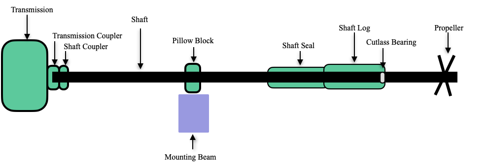
As the shaft is being pulled aft, it slides through 3 components– a Cutlass Bearing, Shaft Seal, and Pillow Block Bearing. Each of these were due for replacement.
Cutlass Bearing
The Cutlass Bearing (John Brad 1-1/2″, 3/8″, 6″) sits at the end of the shaft log and has 3 main purposes:
Shaft Support: It holds the shaft steady inside the stern tube, preventing excessive side-to-side movement.
Friction Reduction: The rubber inner lining allows the stainless steel shaft to spin smoothly without metal-to-metal grinding against the hull structure.
Water Cooling and Lubrication: Internal grooves (flutes) let surrounding seawater flow through the bearing to cool and lubricate the spinning shaft, preventing it from overheating.
Removing the old one was tricky. After an unsuccessful attempt to pull it out with a slide hammer, it had to be cut carefully using a saws-all reciprocating saw. A new one was then tapped into place and secured with 2 grub screws.
Shaft Seal
The purpose of a dripless Shaft Seal (PSS Pro 1-1/2″ x 2-3/4″) is to prevent external water from entering a boat’s hull around the spinning propeller shaft while keeping the bilge completely dry.
The aft end of the shaft seal bellow fits over the stern tube and held in place with 2 large hose clamps. The other end of the bellow has a stationary carbon ring and a rotating stainless steel collar that’s attached to the shaft. The water tight seal is created between the stainless steel collar and the carbon ring from pressure created by the rubber bellow. The hardest part of installing the new one was compressing the rubber bellow to a specified amount (0.75″).
Pillow Block Bearing
A pillow block bearing is used to support the shaft between the shaft log and the transmission. The shaft on Apropos is 12’11” long and could sag in the middle without a pillow block. The bearing is bolted to a fiberglassed wood beam in the bilge. With no height adjustment on the pillow block, the 4 engine mounts must be adjusted up/down to align the shaft to the transmission. The alignment is done by loosening the 4 coupler bolts and using a feeler gauge at the 12, 3, 6, and 9 o’clock positions between the 2 coupler plates. The gaps at the 4 positions should be within 0.004″ (4 mils) of each other. Misalignment can cause wear and early failure of the transmission.
To get the new pillow block bearing in place on the mounting beam, I had to pull up on the shaft. This created a large 10 mil gap at the 6 o’clock (bottom) position between the coupler plates. Ideally, the pillow block would mount lower by about 1/4″, but since it’s mounted to a fixed shelf, that was not possible. Because the shaft had noticeable wear marks where it contacted the pillow block, I decided to change the location of the mount. It would then contact a new part of the shaft, and it could be designed so the pillow block could be lower. This required fabricating a new mounting bracket to moved the pillow block a few inches forward along the shaft. It was also designed to be adjustable up and down to accomodate slight variations in pillow blocks height. The new mounting bracket bolted to the same mounting beam as shown in the drawing below.