Standing rigging on boats should be replaced every 10-15 years, especially for boats taken offshore. The standing rigging on Apropos was 20 years old, so well past its due date for replacement. I decided to perform the job dockside and not pull the masts. This has its plusses and minuses. On the plus side, you can do all the work at the marina and don’t have haulout, mast crane, and yard fees. On the minus side, it takes a lot longer since you can only remove a certain number of shrouds/stays at a time in order to keep the masts from falling down. Apropos, being a ketch, has 2x the rigging and 2x the chainplates and since I planned on doing most of the work myself, I didn’t want to be in a boatyard for a month. There were also lots of variables like the time involved in getting new chainplates fabricated, sourcing custom chainplate bolts, and getting all the swaging work done. I also decided to make this as much of a DIY and learning project as possible. I hired a rigger (Terry from Yachtfitters) for guidance and technical expertise, but did most of the work myself.
Here are the main steps I followed for re-rigging Apropos:
- Tune the rig to spec and mark all the shroud/stay turnbuckles with tape. This is needed to get the proper length for making the new shrouds/stays.
- Remove groups of shrouds/stays strategically. For mizzen shrouds, brace the mast with temporary lines from masthead to deck. For main mast shrouds, remove in groups that allow adequate mast support from remaining shrouds. Deliver shrouds/stays to rigger, whose shop is a 2-minute walk from the marina.
- Remove chainplates associated with the removed shrouds/stays and replace with new. Seal the gaps between chainplates and deck. Replace the chainplate bolts with new.
- Pick up and install the new shrouds/stays from rigger, who did all the swaging work (attach the new wires to turnbuckes at deck end and eyes at mast end).
- Repeat the previous 3 steps until done. I ended up splitting the entire re-rigging into 5 groups of shrouds/stays.
- After all shrouds and stays have been replaced, re-tune the rig back to spec.
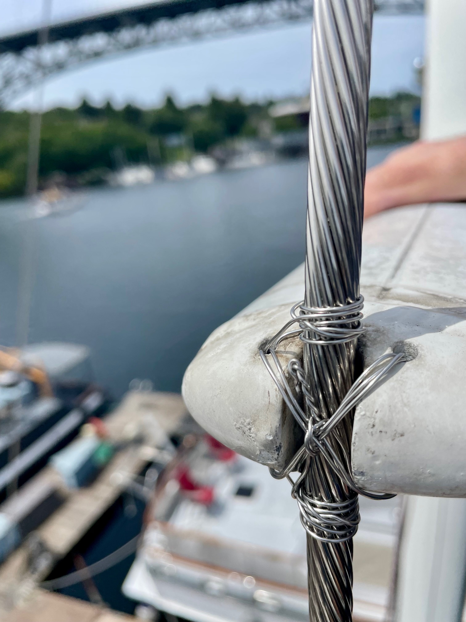
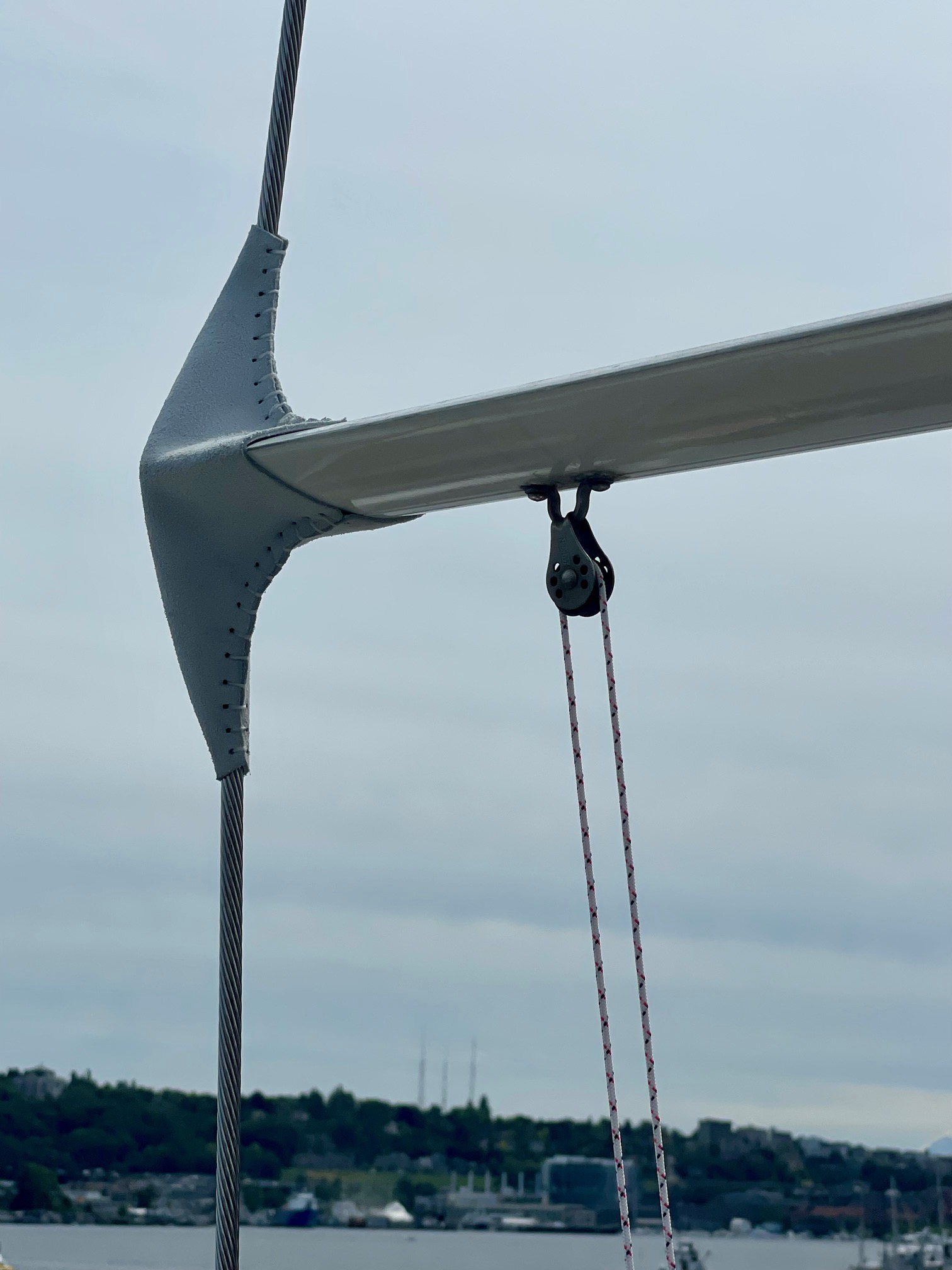
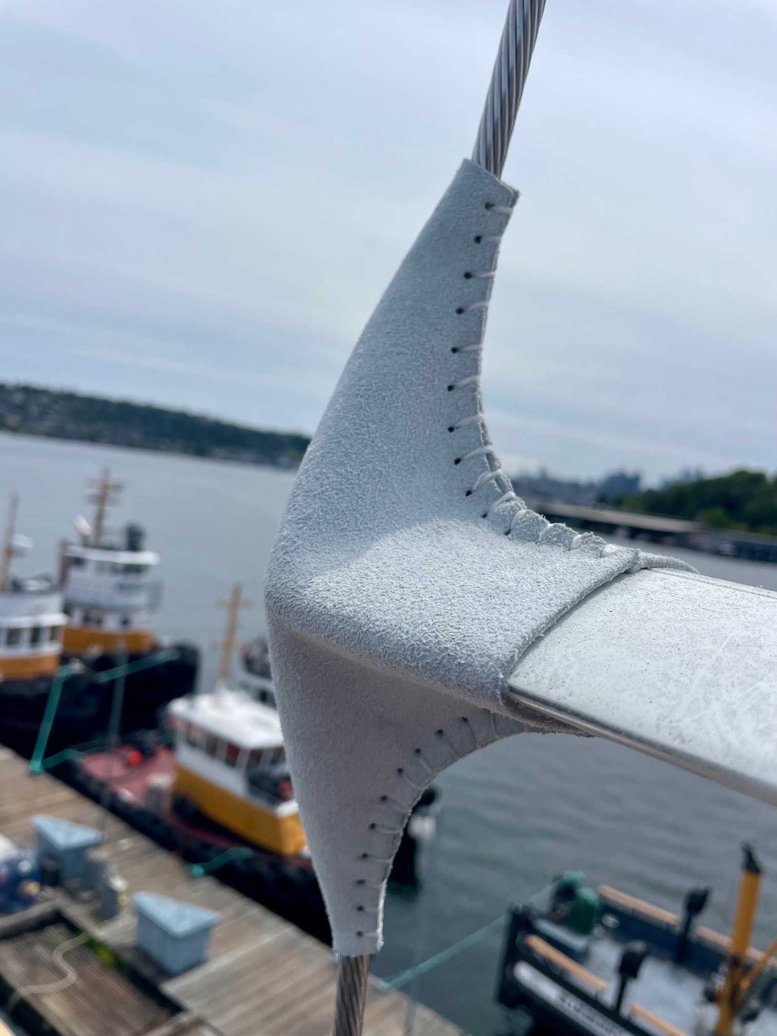
- For cap shrouds, use seizing wire between spreader end and shroud to fix spreader angle. Add leather boots on spreader ends to protect the sails.
The remaining paragraphs provide details on some of the major parts of the project.
Going aloft
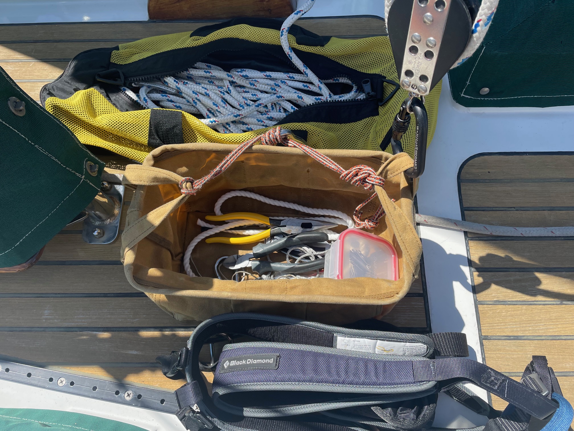
Re-rigging with masts in place requires lots of work aloft. In the past, I was never comfortable going aloft without another person spotting me and taking up slack in the backup/safety halyard. During the project, I probably made 20 trips up the masts. I learned from Terry (professional rigger) how to do it safely. I use a self-made 3:1 block and tackle connected to a climbing harness to go aloft. This allows me to pull myself up the mast with an effort of 1/3 my body weight. What I added to my climbing gear is a fall-arrest device that takes the place of a second safety halyard and the need for a 2nd person. The arrest device connects to my harness and slides up a halyard anchored to the deck. With this, every few feet after I pull myself up a with the 3:1, I slide the arrest device up above my head. If something fails on my main 3:1 halyard, the arrest device will keep me from falling. When I reach the mast level where I’m doing work, I make sure the arrest device is supporting my weight, then I tie off the lazy end of the 3:1 and can use both hands to remove/re-install tang bolts and cotter pins. When working alone, I also use a spare halyard to hoist the shrouds up the mast to the height of where they connect to instead of pulling them up with a messenger line. When removing shrouds/stays, I secure the spare halyard at the level of mast tang before going aloft, then I remove one shroud at a time and secure it to the spare halyard. I also bought a new canvas tool bag that I clip onto my harness that has a rigid top that keeps it open. This makes finding the right tool, tang pin, or cotter pin easier. There’s nothing worse than getting to the top of the mast and not having the correct tool, so I make sure I think everything through before going aloft and double check I have everything needed for the task. Since I made several trips up both mast heads, I took the opportunity to replace both topping lift lines.

Shrouds/Stays
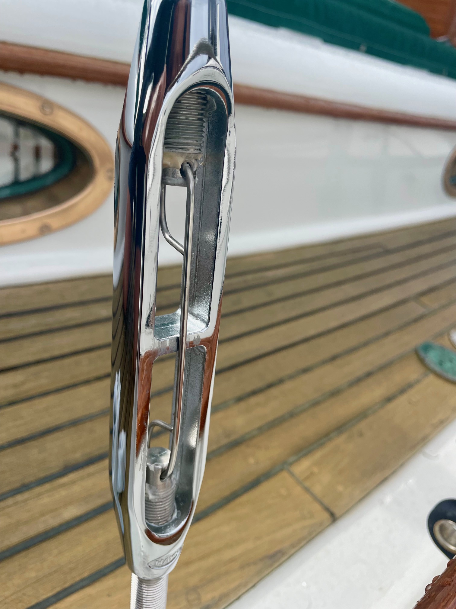
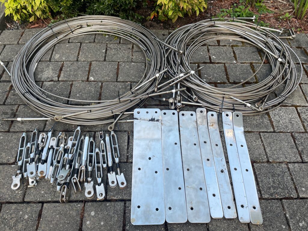
Apropos’ main mast is supported by 8 shrouds, 2 backstays, and 2 forestays. The mizzen mast is supported by 6 shrouds and a jumper stay. The bowsprit has 2 whisker stays and a bobstay. That’s a lot of rigging! All stays are 304 ss wire, with the exception of the bobstay which is solid 1″ ss rod. Most shrouds/stays are 3/8″, a few are 5/16″. All turnbuckles were replaced with high quality Hayn silicon bronze and tefgel was applied to the threads.
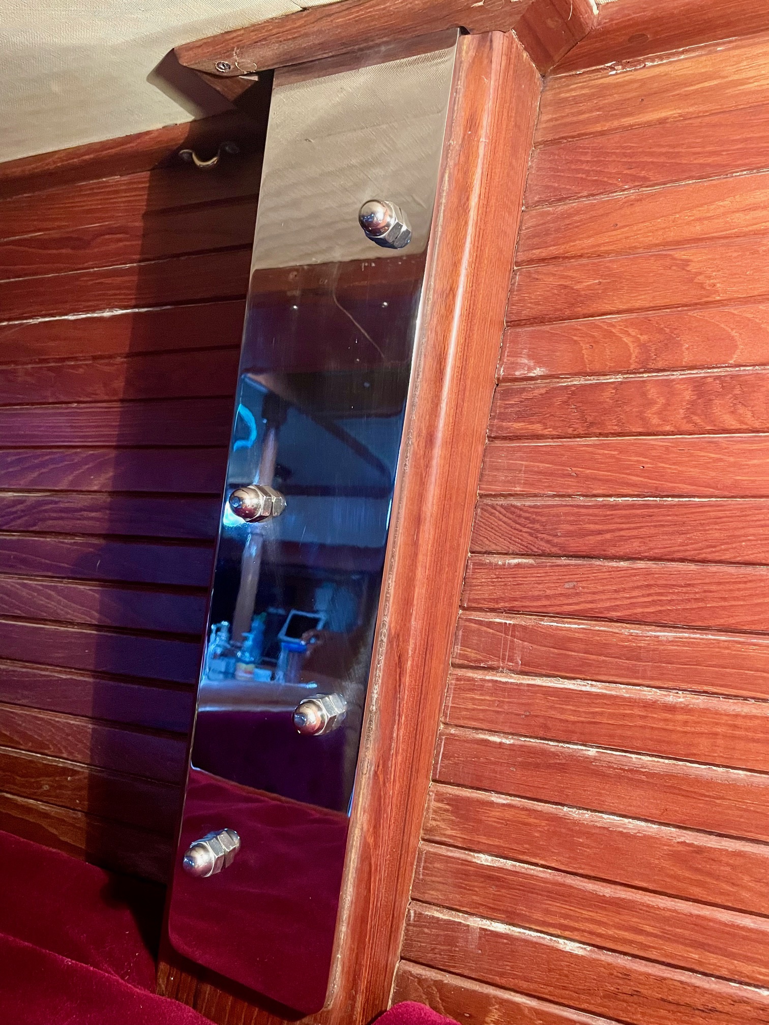
Chainplates
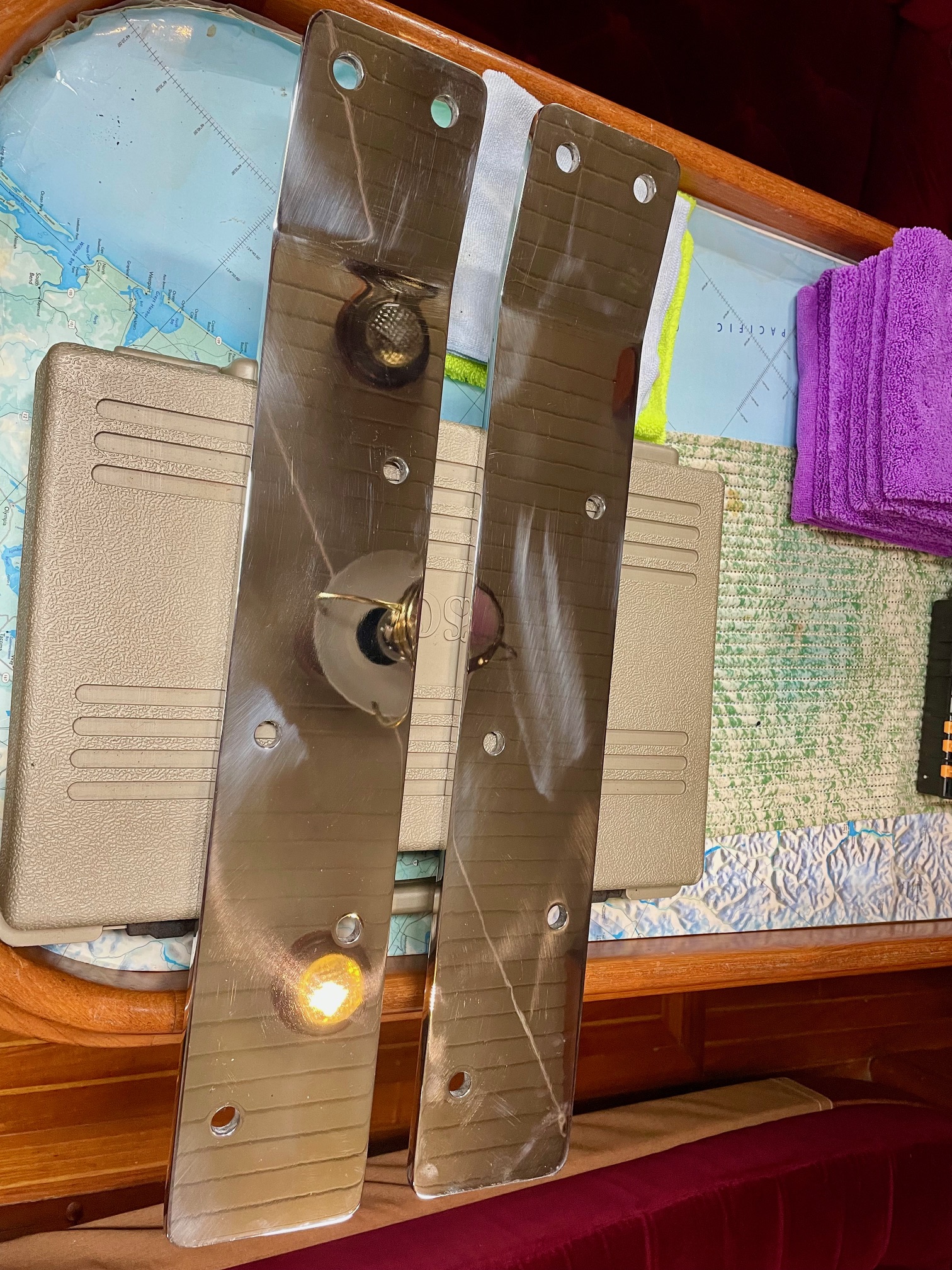
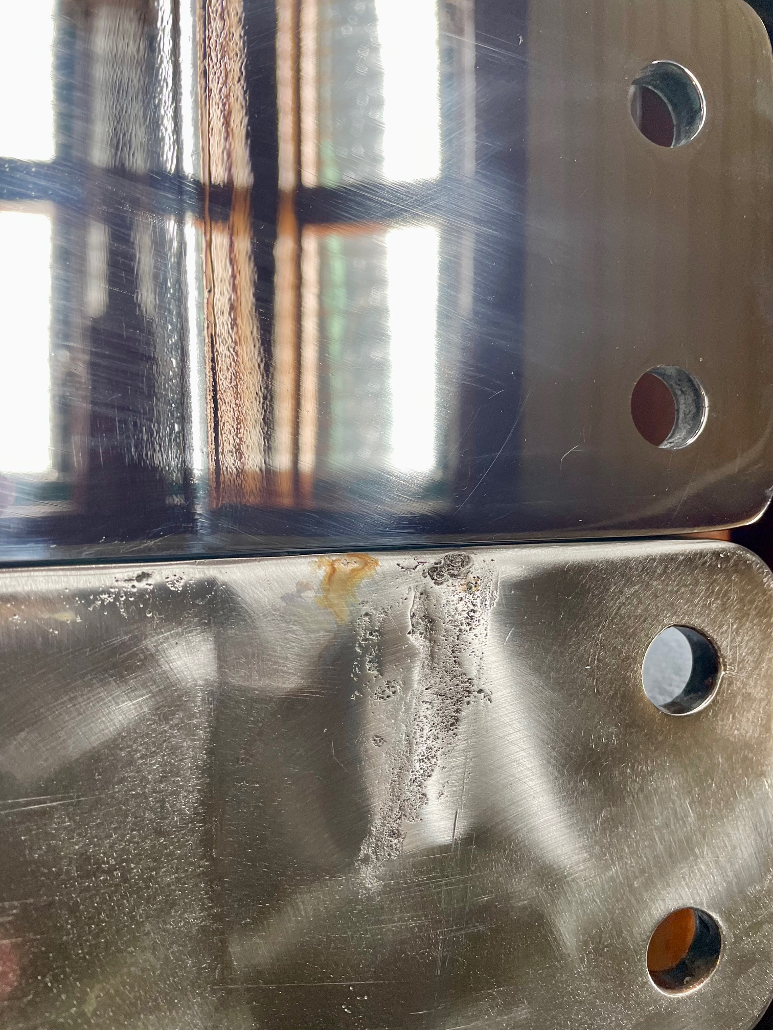
Chainplates secure the shrouds/stays securely to the boat at deck level. On Apropos, they are all internal, which means they go through the deck and bolt on to teak timbers inside the cabin. Even though they are 3/8″ thick 316 stainless steel, crevice corrosion usually occurs in the area between the deck and the opening down below. It’s usually a combination of salt water intrusion and lack of oxygen that causes the corrosion. All the chainplates on Apropos were original, which makes them 42 years old. I had no idea what condition they were in, so I planned to remove all of them to inspect & replace.
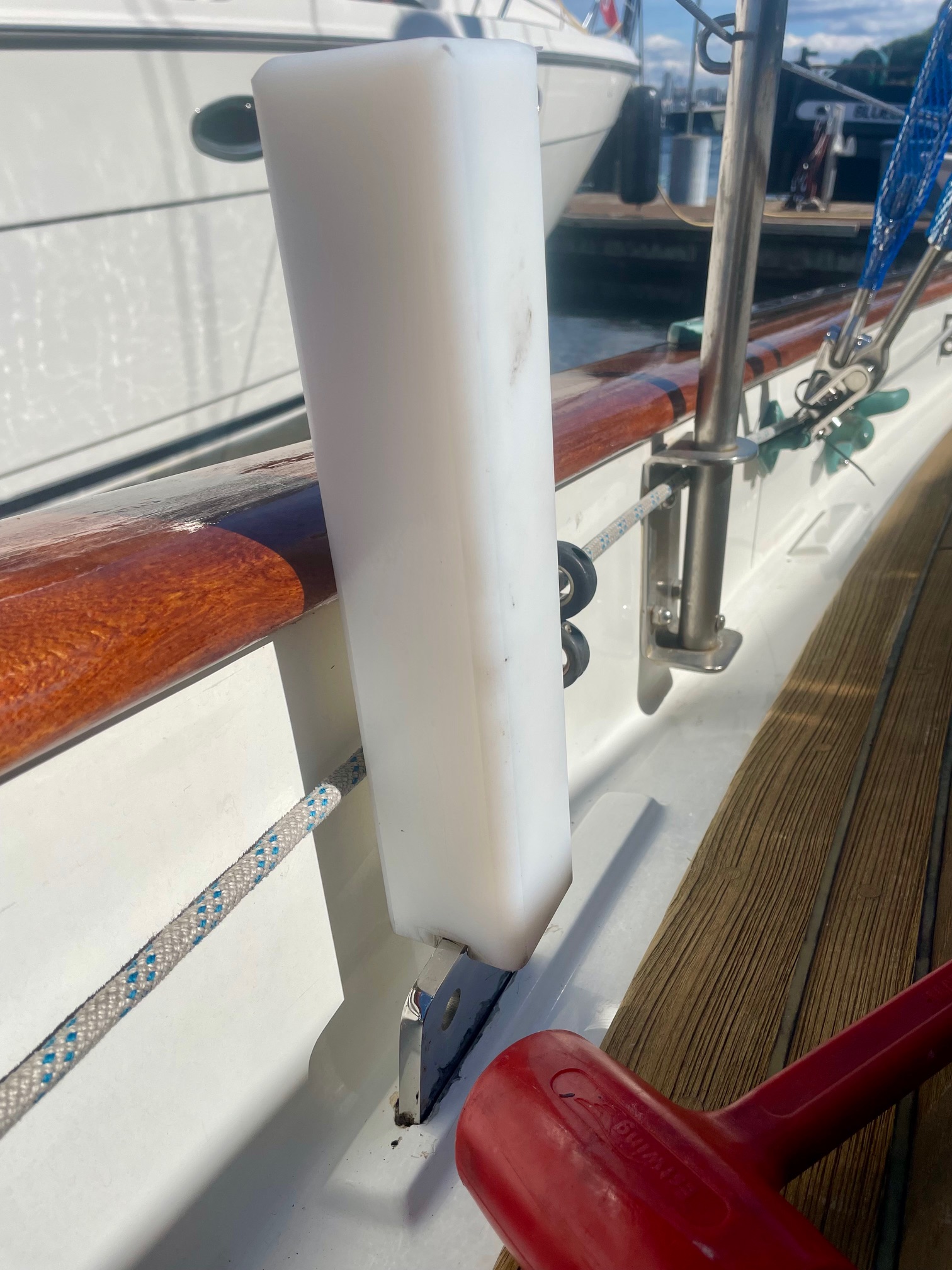
Removing
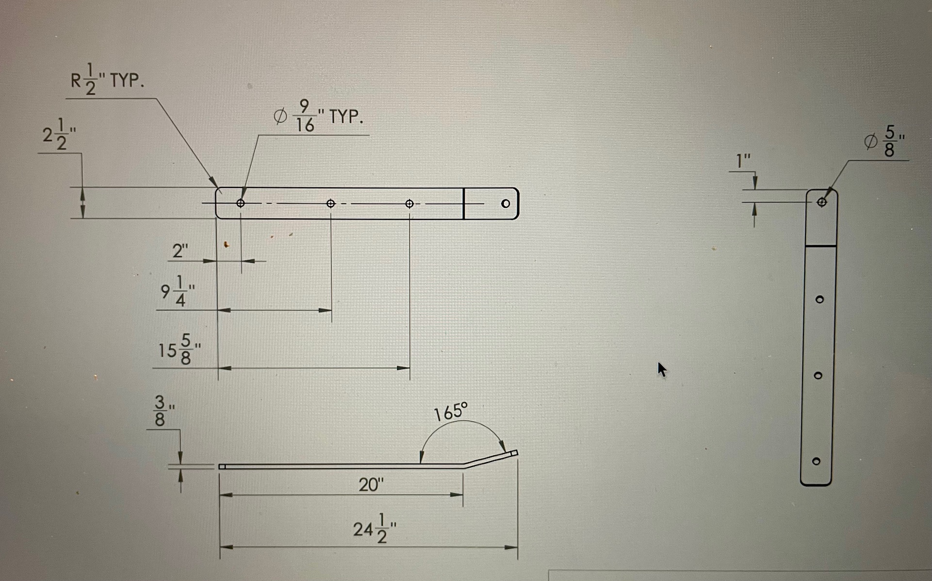
Removing the 10 chainplates was no easy task. There are 2 triples (for 3 shrouds) that are 6.5″ wide, 2 doubles (for 2 shrouds) that are 4.25″ wide, and 6 singles (for 1 shroud) that are 2.5″ wide. Each chainplate has an approximately 166 degree bend, which is the angle between the hull sides and the shrouds. Because the bend is inside the core, the chainplates need to be removed downwards, often with a lot of force. I used blocks of wood and a heavy mallet to pound them down from above. The triples were by far the most difficult to remove and the wood blocks kept splitting, so I made a 2.5″ x 2.5″ x 12″ piece of UHMW polyethylene with a 3/8″ notch routed on the bottom to help pound the chainplates down. Because of the bend in the chainplates, removing them caused the outboard edge of the raised deck piece to break off. After re-installing the new chainplates, I used thickened epoxy to reattach them.
Fabricating
Garhauer Marine fabricated and mirror-polished the new chainplates from 316 stainless steel. They have reasonable prices and great customer service. I supplied them with detailed drawings and they all fit perfectly.
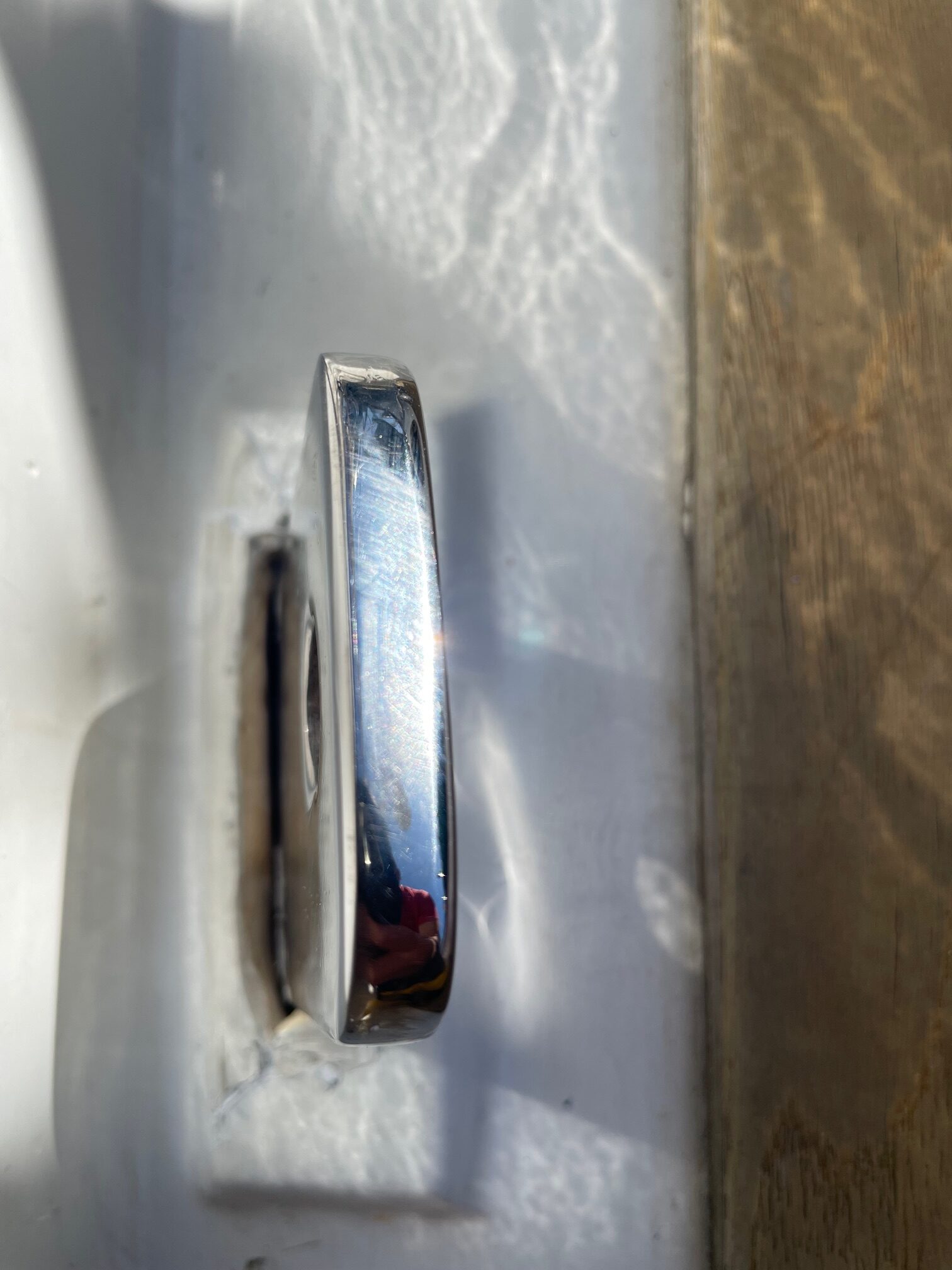
Sealing
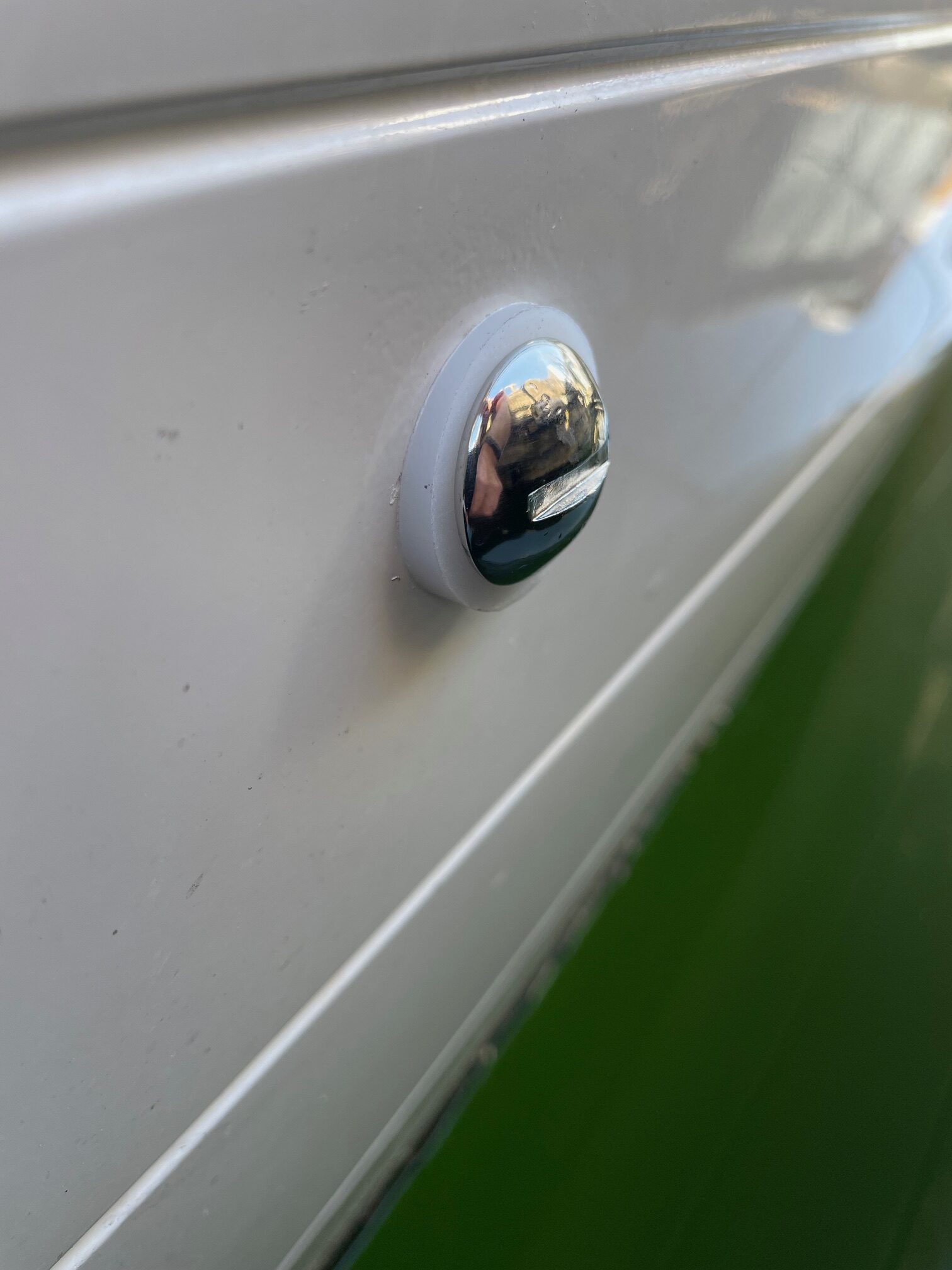
It’s important to have a good water-tight seal around the chainplates at deck level. I like to do the sealing before attaching the shrouds for easier access. Here are the steps I followed:
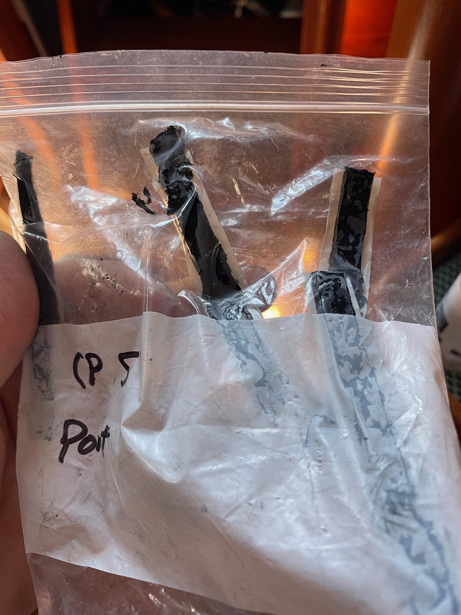
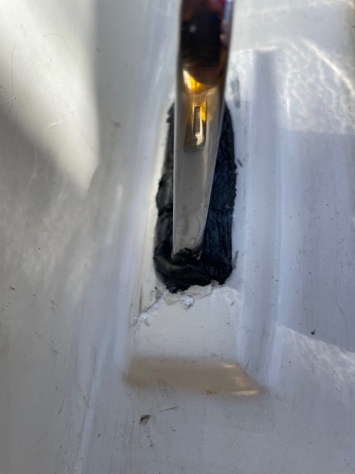
- Clean the area around the chainplate with acetone
- Apply black butyl rubber (McMaster-Carr #75875A661) along both sides of the chainplate and at both ends. The black butyl is extremely tacky, so put pre-cut strips inside a ziplock back and place it in the refrigerator for 15 minutes. It’s best to leave the paper strip on, then push it into the gaps between the chainplate and deck and then peal off the paper.
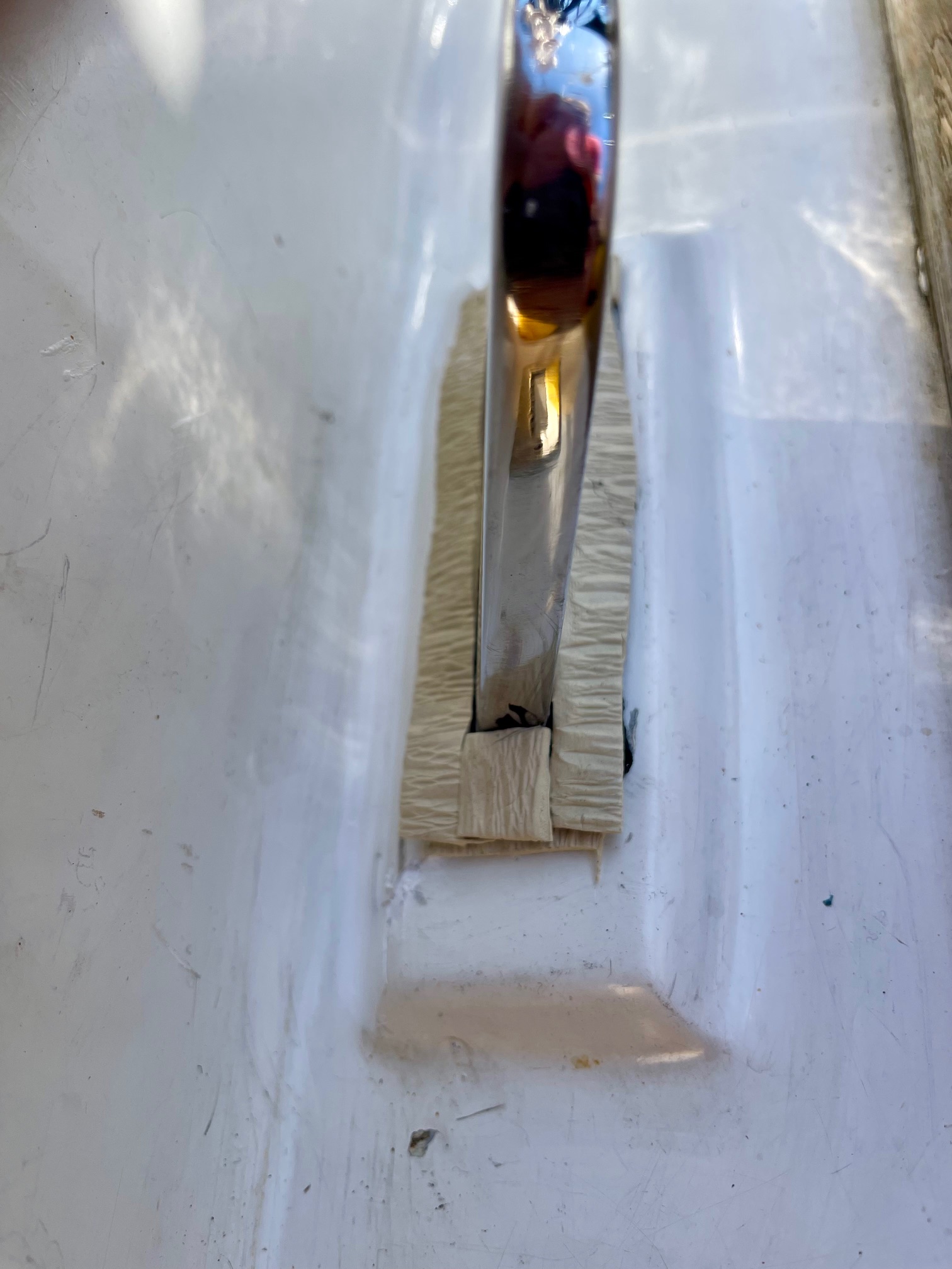
- Apply white butyl (clay-like, non hardening McMaster-Carr #9408T146) overtop the black, along both sides and at both ends. Since the white butyl doesn’t stick to your fingers, use it to push more of the black butyl into the gap. On colder days I like to use a heat gun to warm the chainplate and butyl slightly.
- Fasten the stainless steel cover plate and secure with 2 ss screws. It helps to push down on the cover plate as screws are being tightened. A little heat can also help to compress things and get a good seal. The plate will not be flush against the deck, it will be raised slightly because of the white butyl. Trim off any butyl as necessary.
This process should give a watertight seal. So far none of the 10 chainplates have leaked.

Bolts
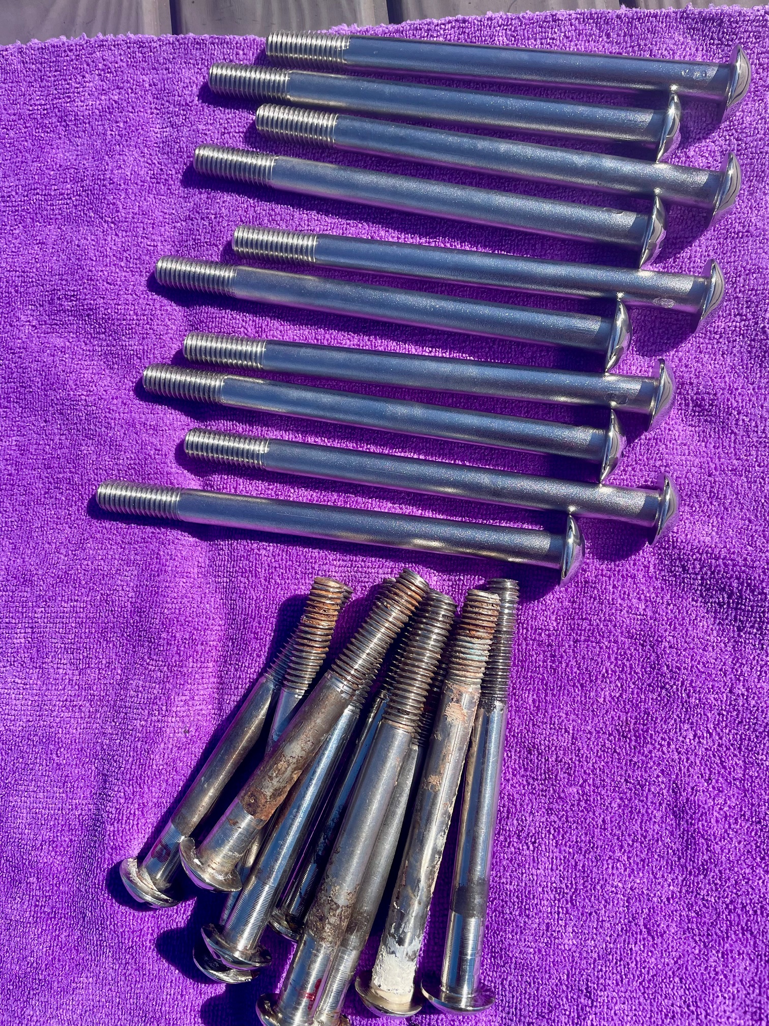
Most of the 36 bolts that secure the chainplates to the hull showed signs of corrosion. I replaced them with new custom made 316 stainless steel 1/2″ bolts. The new bolts started out as carriage bolts and were machined to remove the square under the head, then a slot was milled into the head and threads were cut. Since the bolts came from stock, I polished the heads to a mirror finish. I ordered 2 sizes, 6-3/4″ and 5-5/8″ lengths, both with 1-1/2″ of threads. With these 2 lengths I was able to custom fit each one by cutting the length with an angle grinder. The heads on the original 16 bolts for the 4 stern chainplates were bent to account for the angle difference of the hull and bolt . Instead of trying to bend the heads of the new bolts, I decided to make custom tapered washers. I bought a 2 foot long tube of Tivar UHMW polyethylene 1-1/4″OD, 5/8″ ID (McMaster-Carr #8705K91) and used a chop saw to cut the washers. Each one had to be custom fit with taper angles between 3 and 10 degrees.
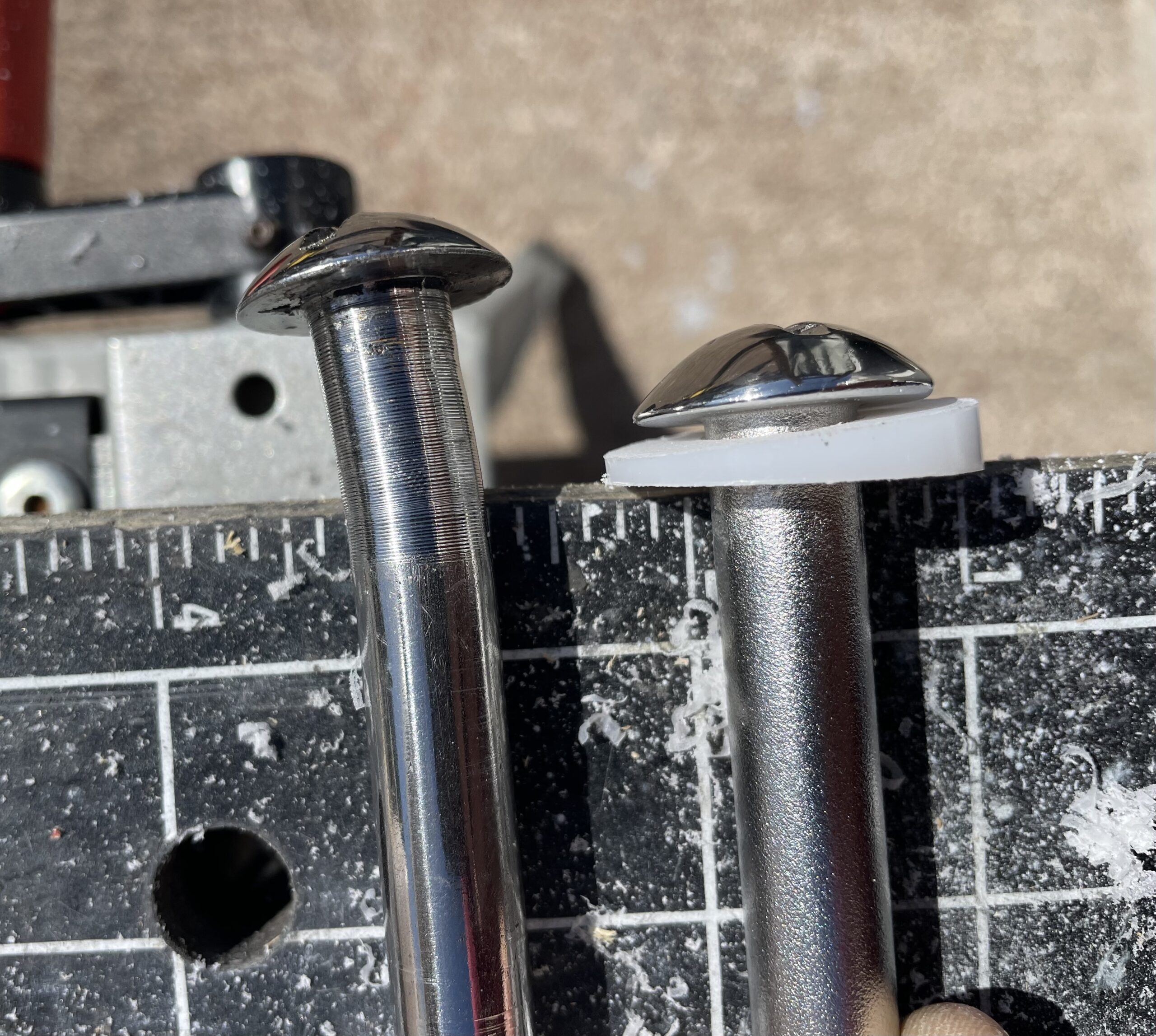
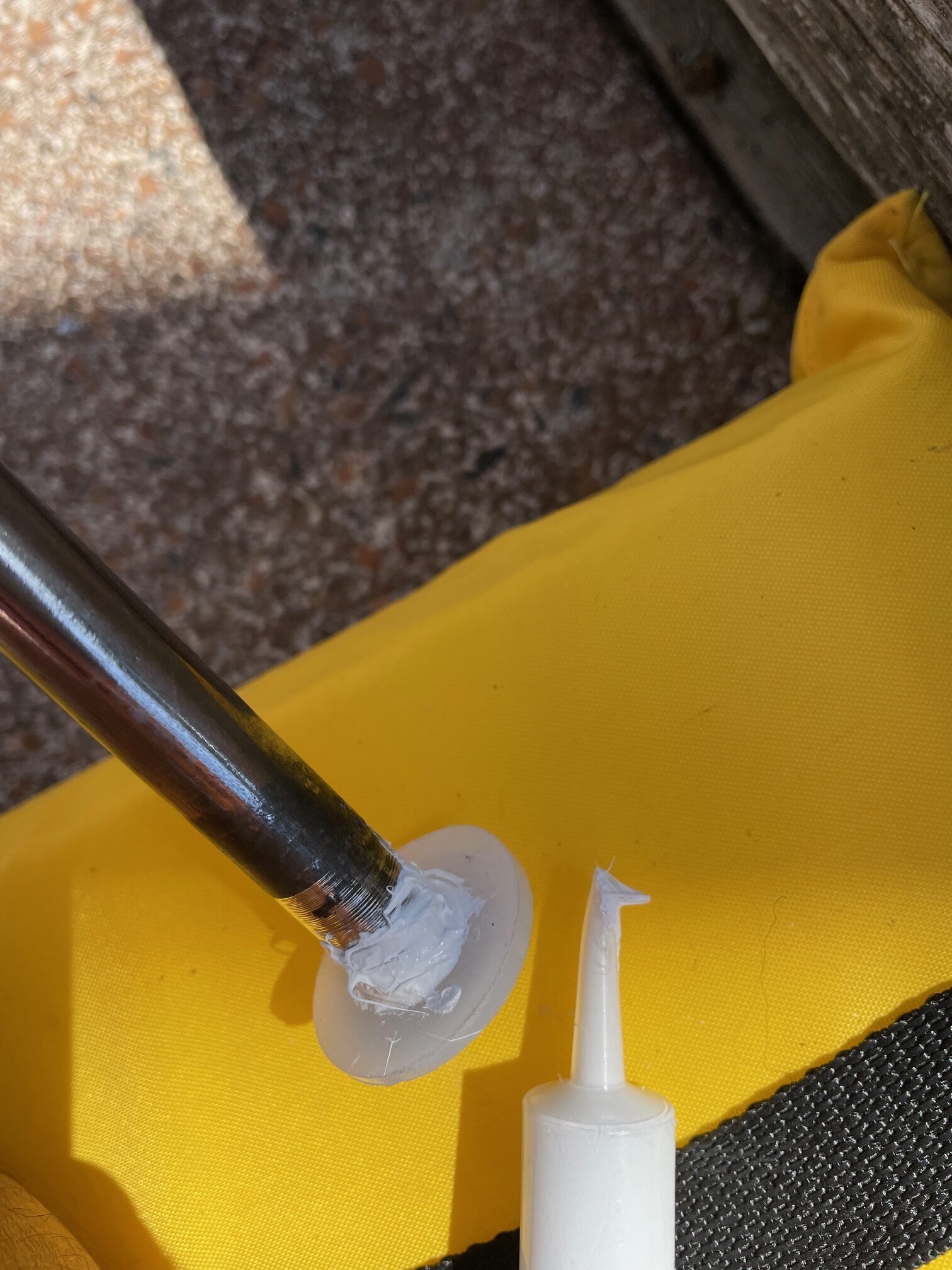
When installing the bolts, I used a bead of white Sikaflex 291 marine sealant between the washer and hull. I aligned each bolt orientation with the slot horizontal.
Final Rig Tuning
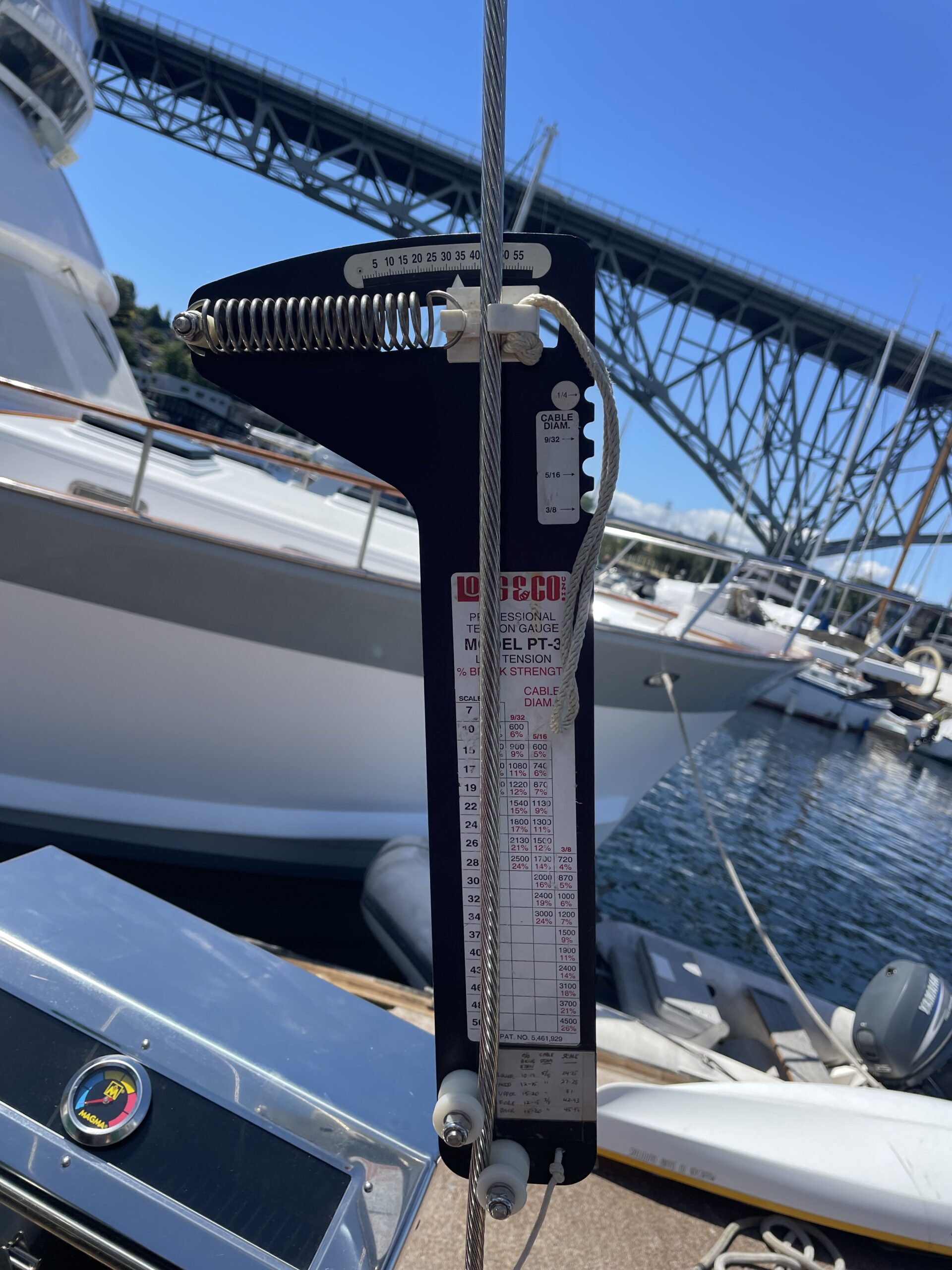
Rig tuning is done by adjusting turnbuckles to get the proper tension on the shrouds/stays. A good rigger knows the proper tensions for each particular shroud/stay–cap shrouds, backstays, fore-stays, intermediates, and lowers. A tension gauge (Loos & Co. Model PT-3) is used to measure wire tension. It works by measuring the deflection along a 12″ section of the wire with a spring. As the wire tension is increased, the readout (scale from 0 to 60) goes up. A convenient table printed on the gauge is used to convert the scale to lbs tension and % break strength. In the picture below, the readout is 34 on 3/8″ wire, so the lbs tension is 1200 and the % break strength is 7.
There’s another component to rig tuning besides using a tension gauge and adjusting turnbuckles. An experienced rigger constantly monitors the mast for shape. This is done by sighting up the mast from all 4 sides. The art comes in by knowing which shroud/stay to adjust to produce the intended change in the mast bend. It’s also important to get the spreader angles even. This can be done by measuring from each spreader tip to the deck. Each spreader can be bumped up/down until port and starboard tips are equal distance to the deck. Next stainless steel wire is used to seize the shroud at the spreader tip, which locks the spreader angle in place. The final step is to place spreader boots on the tips to protect the sail when it comes in contact with the spreader. I decided to use leather boots instead of the rubber type that was on the boat before. The leather boots need to be stitched on using a herring-bone stitch, which took about 30 minutes each. Instead of a climbing harness, I used a bosun chair which is way more comfortable for the 2 hours it took to stitch on 4 spreader boots.
Pinning the turnbuckles is typically done with cotter pins. Another method is using stainless steel welding rod. This gives a cleaner look and prevents snagging lines.
Here are the wire sizes and specs for the final rig tuning:
- Main mast cap shroud 3/8″ wire, 44 or 15%
- Main mast fwd lower 3/8″ wire, 42 or 13%
- Main mast aft lower 3/8″ wire, 38 or 10%
- Main mast intermediate 5/16″ wire, 23.5 or 10.5%
- Main mast backstays 3/8″ wire, 34 or 7%
- Main mast inner forestay 3/8″ wire, 35.5 or 8%
- Main mast headstay 3/8″ wire
- Mizzen mast fwd 3/8″ wire, 41 or 12%
- Mizzen mast lower 5/16″ wire, 21 or 8.5%
- Mizzen mast cap shroud 5/16″ wire, 26 or 12%
- Mizzen mast jumper stay 1/4″ wire, 7 or 5%
- Bowsprit whisker stays 3/8″ wire, 38 or 10%
Conclusion
The project took about 2 months from start to end. It involved a lot of custom fabrication, plenty of trips up & down the masts, and hours working aloft. It was a good learning experience and something I shouldn’t have to repeat again on Apropos. Replacing the standing rigging and chainplates will give me some peace of mind when sailing offshore in heavy weather conditions.
300 lbs of old rigging!