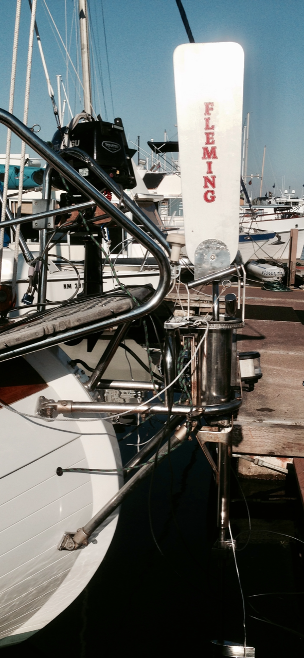
Apropos came with a Fleming Servo-Pendulum windvane. It was an older version (1980’s) and heavily built of stainless steel. I mounted it on the stern with existing hardware and eventually learned how to use it. A servo-pendulum system steers the boat relative to the wind by deflecting a vane that pivots a paddle in the water. As it pivots, the water pressure swings the paddle in a pendulum motion, moving lines running from the windvane to a drum attached to the wheel. This turns the wheel and hence the boat rudder. We sailed thousands of ocean miles with “Ian” doing the majority of the steering. As with any windvane, having a balanced boat is the most important thing.
Here are some of the problems we encountered with Ian.
- The path the control lines take from the windvane to the wheel are through the hull into the lazerette, into the cockpit, and to a drum attached to the wheel. Three sets of blocks were used along the way but there was still a lot of friction. Enough apparent wind was needed to overcome the friction to make it work. On long ocean passages, this wasn’t too much of an issue. But chafing of the control lines and getting the proper tension on the lines were constant struggles.
- Wear and tear on the boat’s steering system was another concern. In action, a servo pendulum system is constantly turning the wheel back and forth by small amounts for course correction. Even though the rudder is only moving by small amounts and the boat is sailing relatively straight, there’s constant movement of the steering system.
- An unexpected mishap occurred during an offshore passage from Kiribati to Hawaii, when a weld joint on the paddle failed and the paddle sunk to the bottom of the ocean. We were 8 days into a 10 day passage, so we hand-steered the rest of the way. Even though Fleming is no longer making windvanes, they still had parts and I was able to have a new paddle shipped to Hawaii and had it welded back onto the shaft. It worked on a windy 20 day passage from Hawaii to Seattle. But the point is, 35-year old equipment is bound to have problems and I didn’t trust it anymore.
- The vane adjustment was difficult to use. It has a ratcheting 360 degree vane with 120 teeth to provide 3 deg adjustment. I extended 2 lines as toggles so you didn’t have to reach all the way back to the windvane to adjust it, but it was still a bit clunky to use.
New Hydrovane Windvane
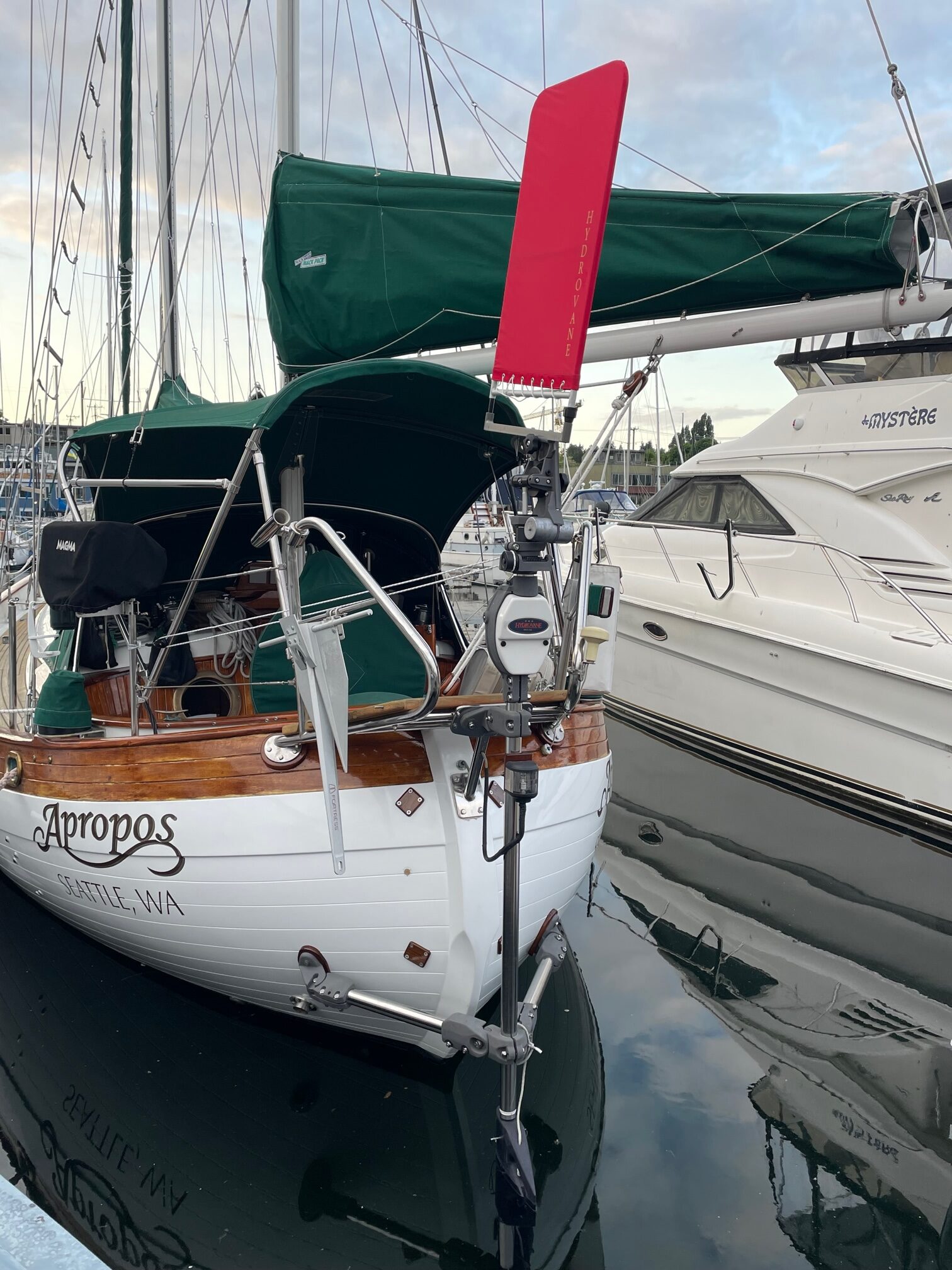
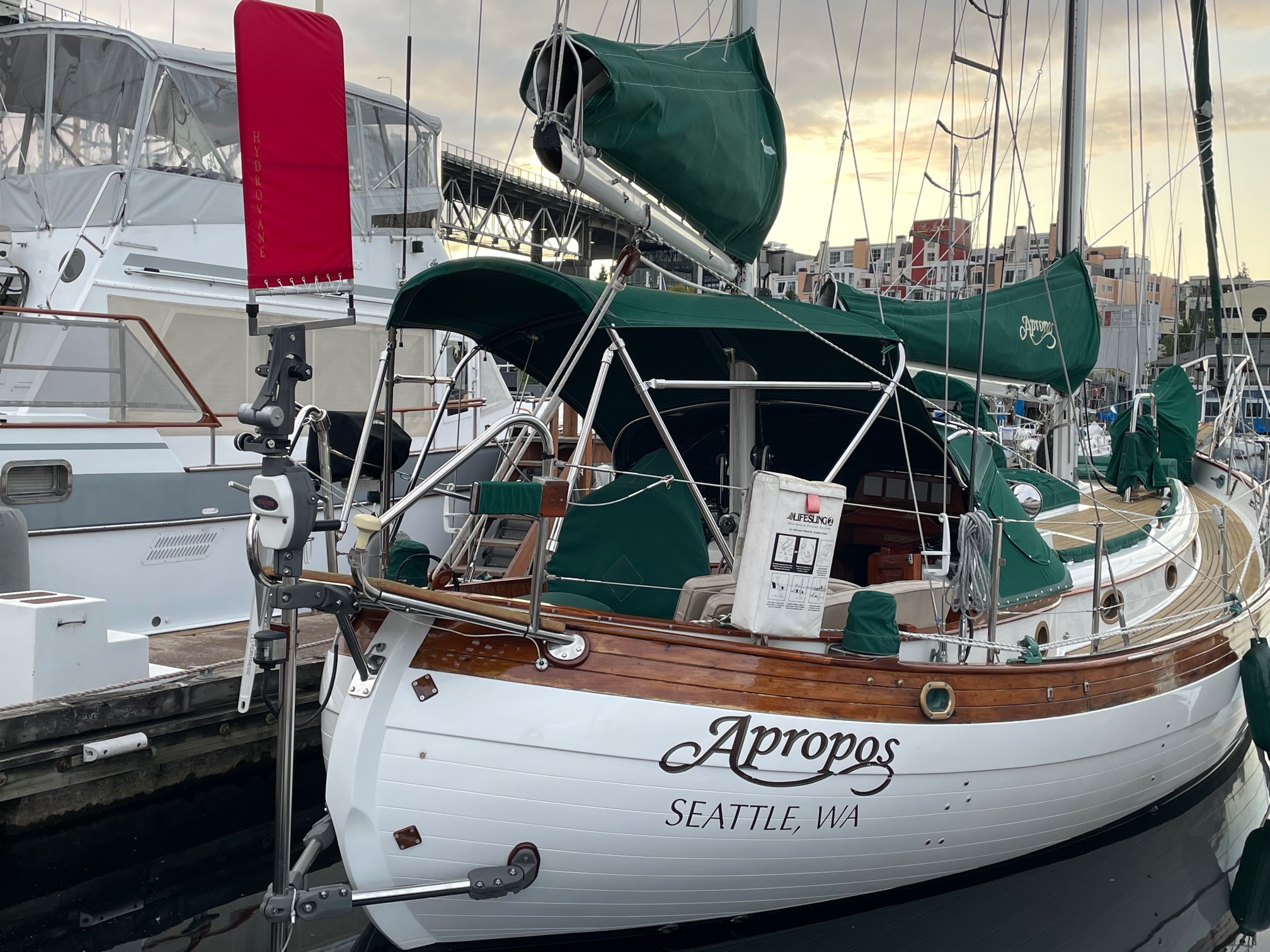
A Hydrovane self-steering windvane is an auxiliary rudder type system that drives its own rudder via a sophisticated drive unit linkage. Both the vane and the rudder are larger than the vane and paddle used in a servo-pendulum system. There’s an adjustment called a ratio knob that can be set according to wind conditions. The vane can also be adjusted up & down as well as pivoting to fine tune the sensitivity. The vane rotates 360 degrees via a continuous control line that extends into the cockpit, making it easy to adjust while at the helm.
Installation
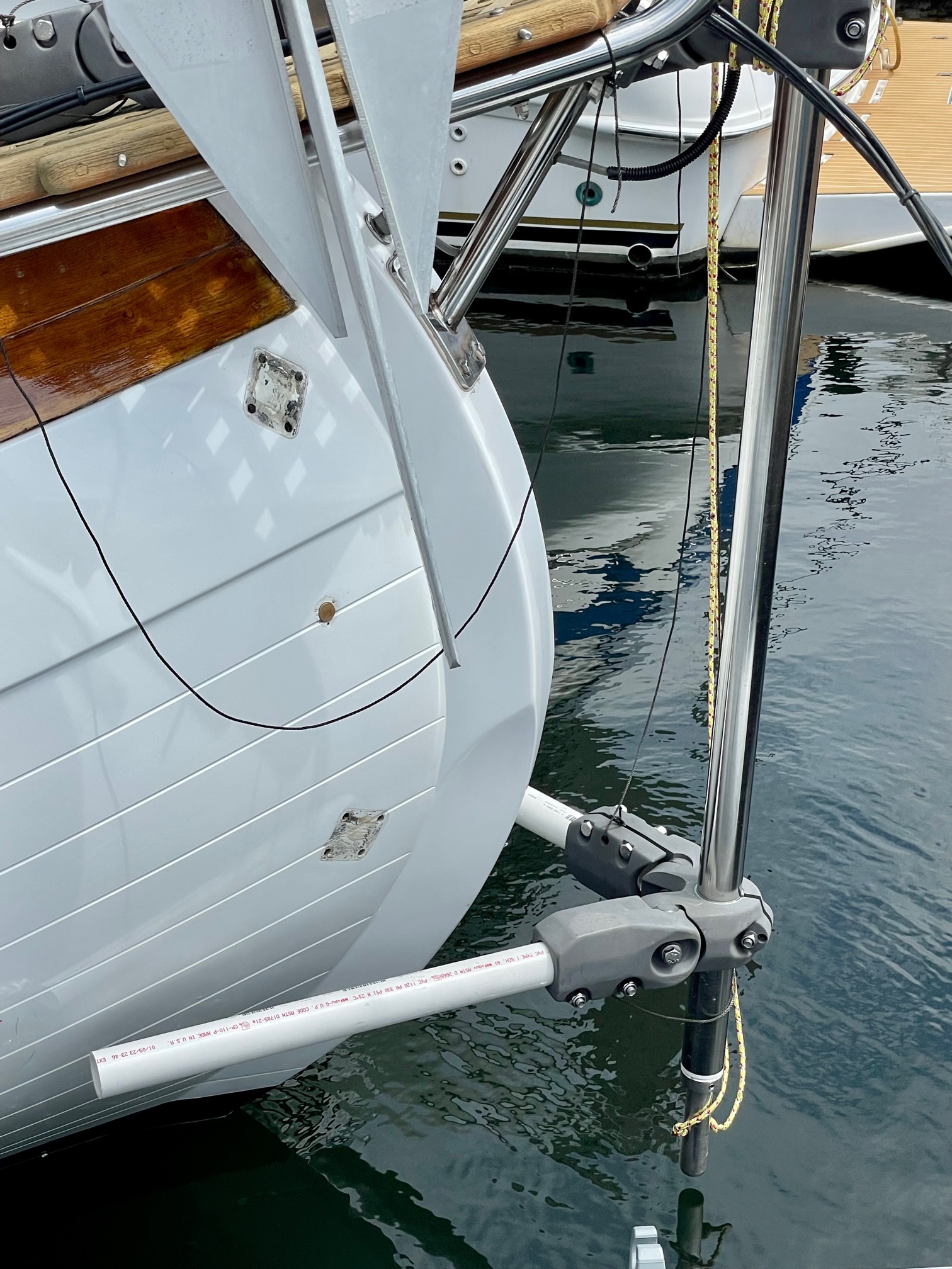
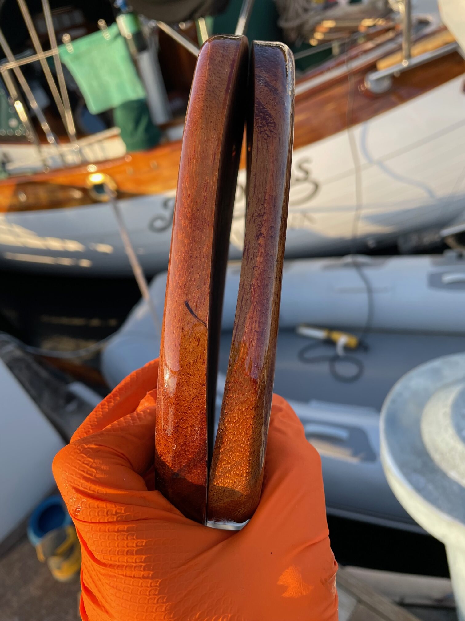
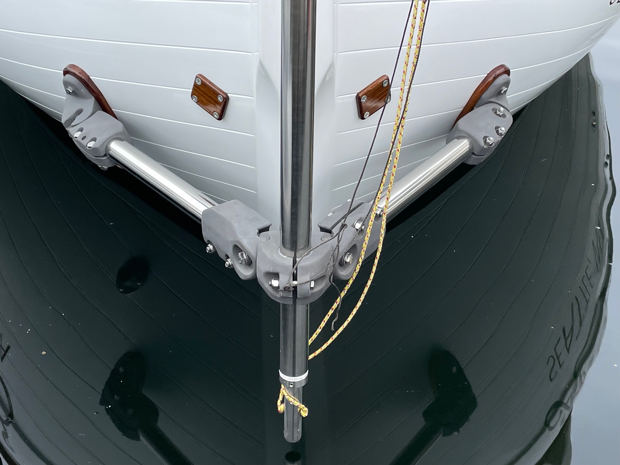
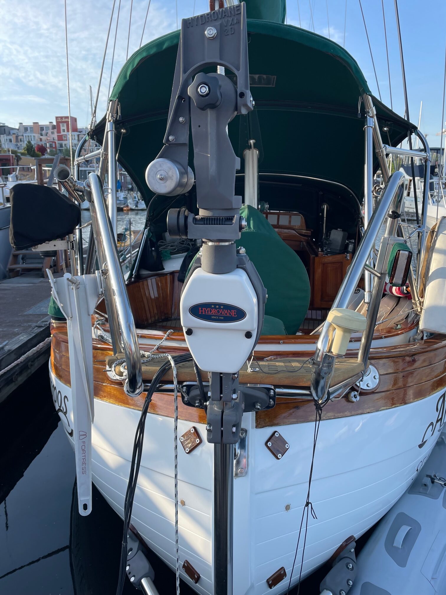
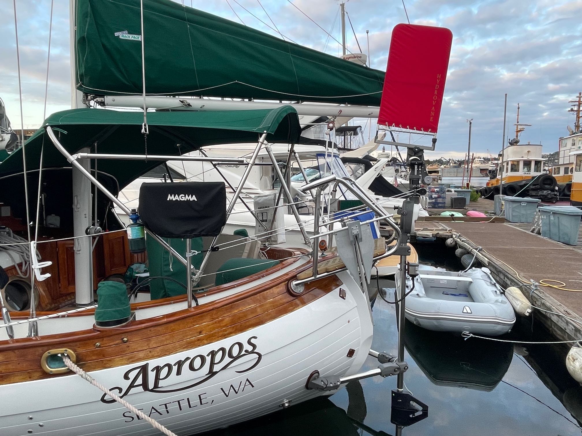
Although the Hydrovane can be mounted off-center, I decided to mount it on the centerline of the boat. Hydrovane provides the correct brackets and shaft needed for any boat, and for Apropos I needed an upper H bracket, a lower A bracket, and a longer shaft, and 2 mounting brackets, teak pads and backing plates. For every step of the installation, I tied safety lines to the parts in case something fell. I was able to work from the dock when installing the upper H bracket, and from a dinghy for the lower A bracket. The install instructions (booklet and video) provided by Hydrovane were very well done and easy to follow. Phone support from Richard and Will at Hydrovane was also very helpful with any questions I had.
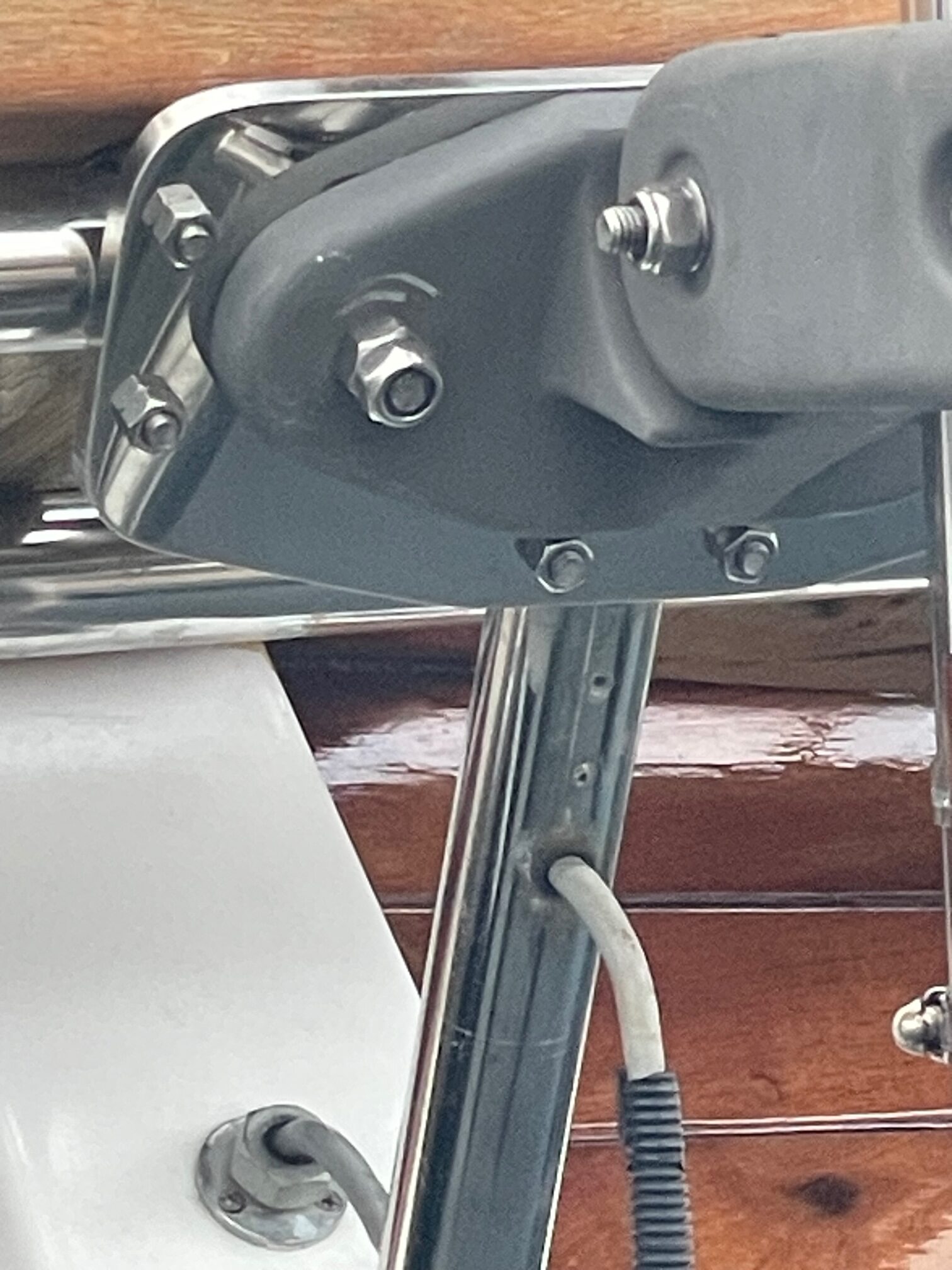
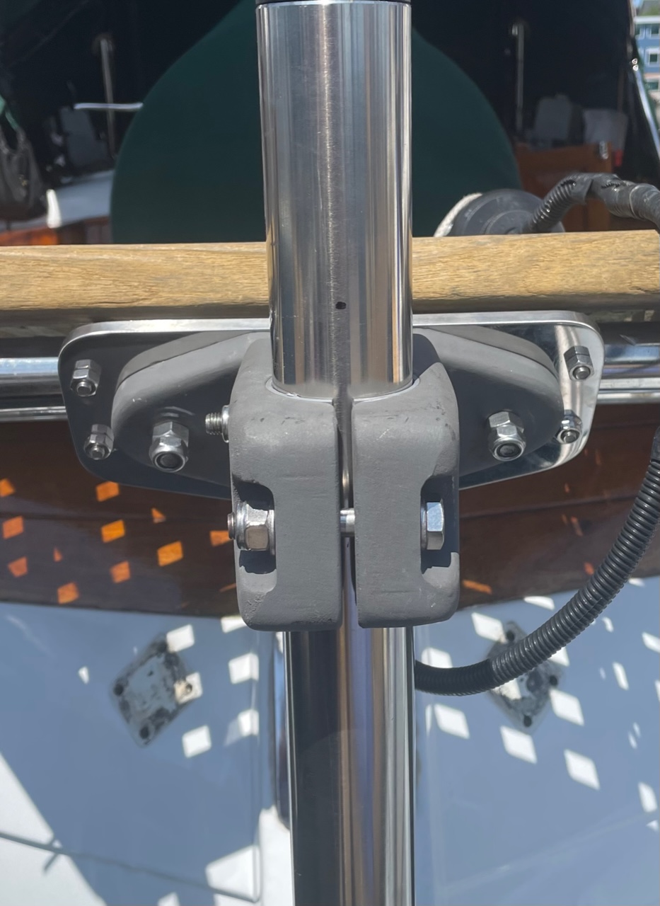
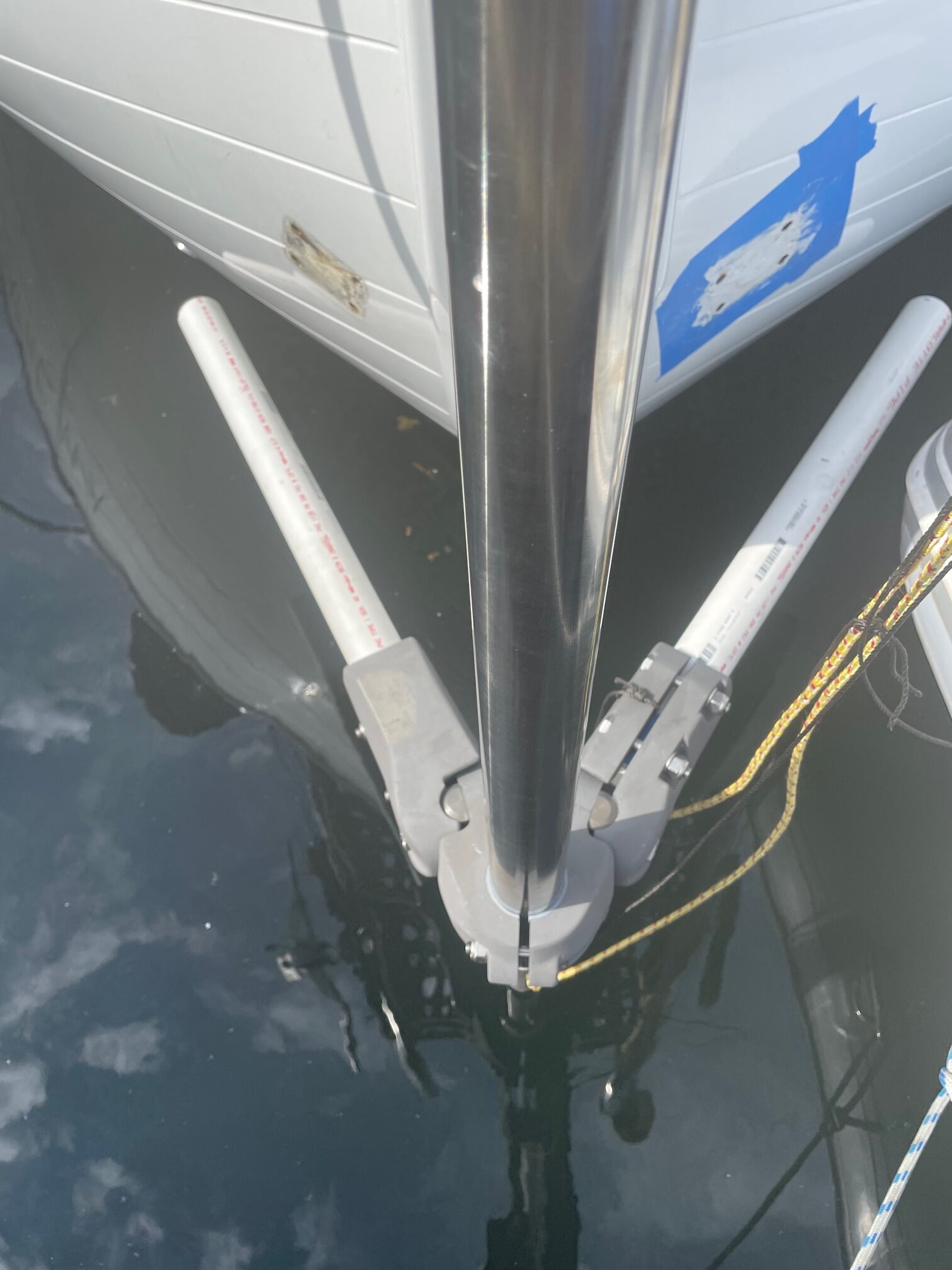
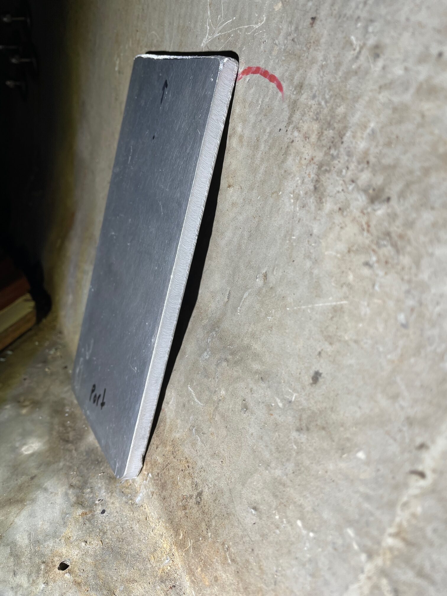
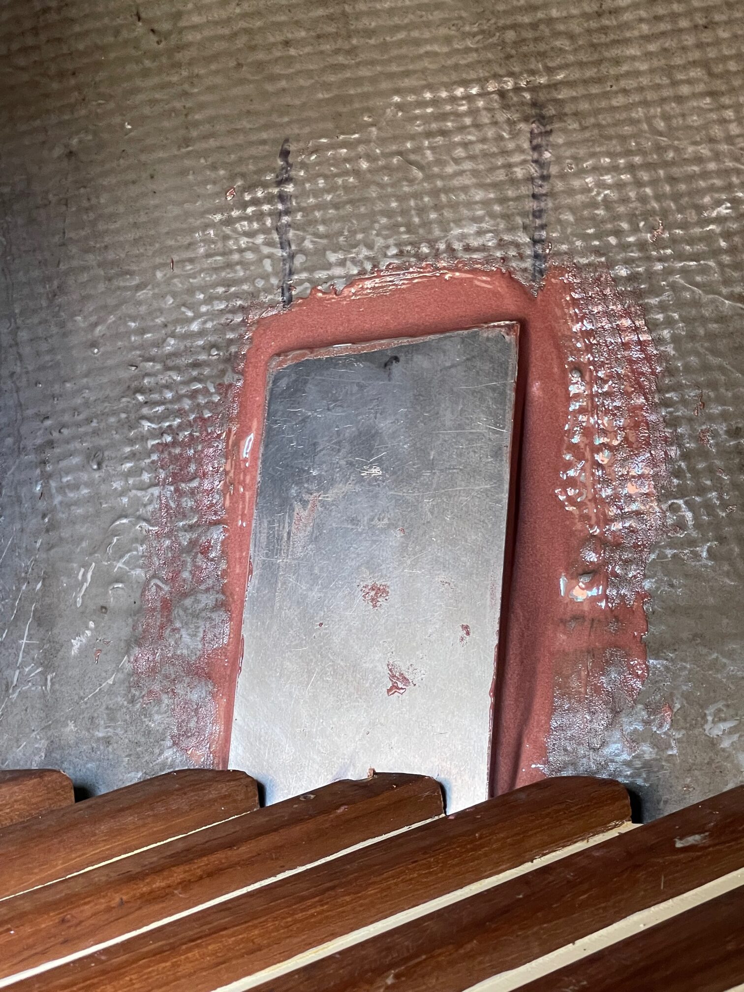
For the upper H bracket, I had a custom stainless steel plate fabricated and mounted it to the stern platform with 3 U-bolts. The H bracket then got bolted to the plate for a very solid upper connection. Next I mounted the shaft to the H bracket. For the lower connection, an A bracket was used with SS tubes extending to mounting plates that through-bolted to the hull. I used 3″ pvc pipe in place of the SS pipe for determining the exact placement of the hull through-bolts. One of the most time-consuming parts was sanding the 2 teak pads that fit between the hull and mounting plates to the contour of the hull shape. For this, I taped 80 grit sandpaper onto the hull and moved the teak pad back and forth until there were no gaps (took over 2 hours per pad). I used aluminum backing plates inside the hull, and fastened them using thickened epoxy to increase the contact area of the plates. After the upper H bracket, shaft, and lower A bracket were all mounted, the drive unit was added to the top part of the shaft, and finally the rudder, vane and vane adjustment line. Here are some pictures taken during the installation.