I completed a lot of boat projects during the winter and spring. Some were left over from things that broke during our trip to the South Pacific, and some were completely new. Some projects took a day to complete and others took weeks. Here is a partial list:
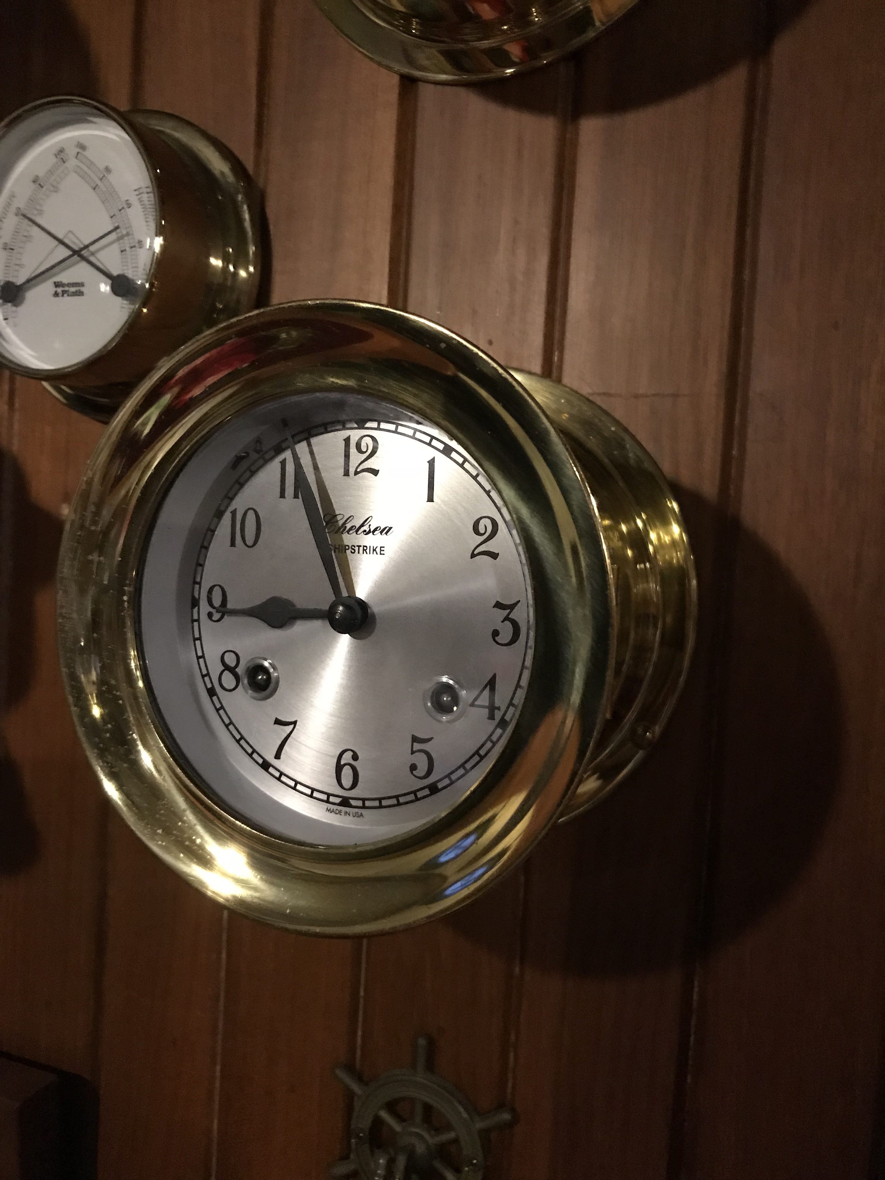
- Chelsea Shipstrike Clock–the 10 year old mechanical clock worked intermittently by the end of our trip. When it stopped ticking, sometimes removing it from the bulkhead and shaking it would restart it. But eventually it stopped altogether. I got quotes from a local repair shop of $400 which included taking it apart to clean and lubricate. That seemed like way too much for a clock that sells for around $800. So, a bit of YouTube research, a $10 bottle of clock oil, and a few hours of my time was all that was needed to get the clock ticking again.
- Bilge Pump–the secondary bilge pump that turns on first to remove water from the bilge was an old diaphragm pump with a 12VDC motor with brushes! Probably original equipment so it must have been over 30 years old. During our trip I replaced the belt and internal diaphragms with a rebuild kit I brought along. The pump got a real good workout on the wet passage from Hawaii to Seattle with lots of water on the deck finding its way to the bilge. It also had an inline filter that I had to clean often because it was getting clogged up with dead cockroaches! Anyhow, I decided to replace it with a new pump that is half its size and pumps twice the GPH. The Whale Supersub Smart pump has automatic water sensing that uses no moving parts, and was easy to install. Since this pump sits in the bilge (the old one was located outside the bilge and had a hose going to the bilge), it required running new wiring and a new hose to a thru-hull. Total cost was about $125.
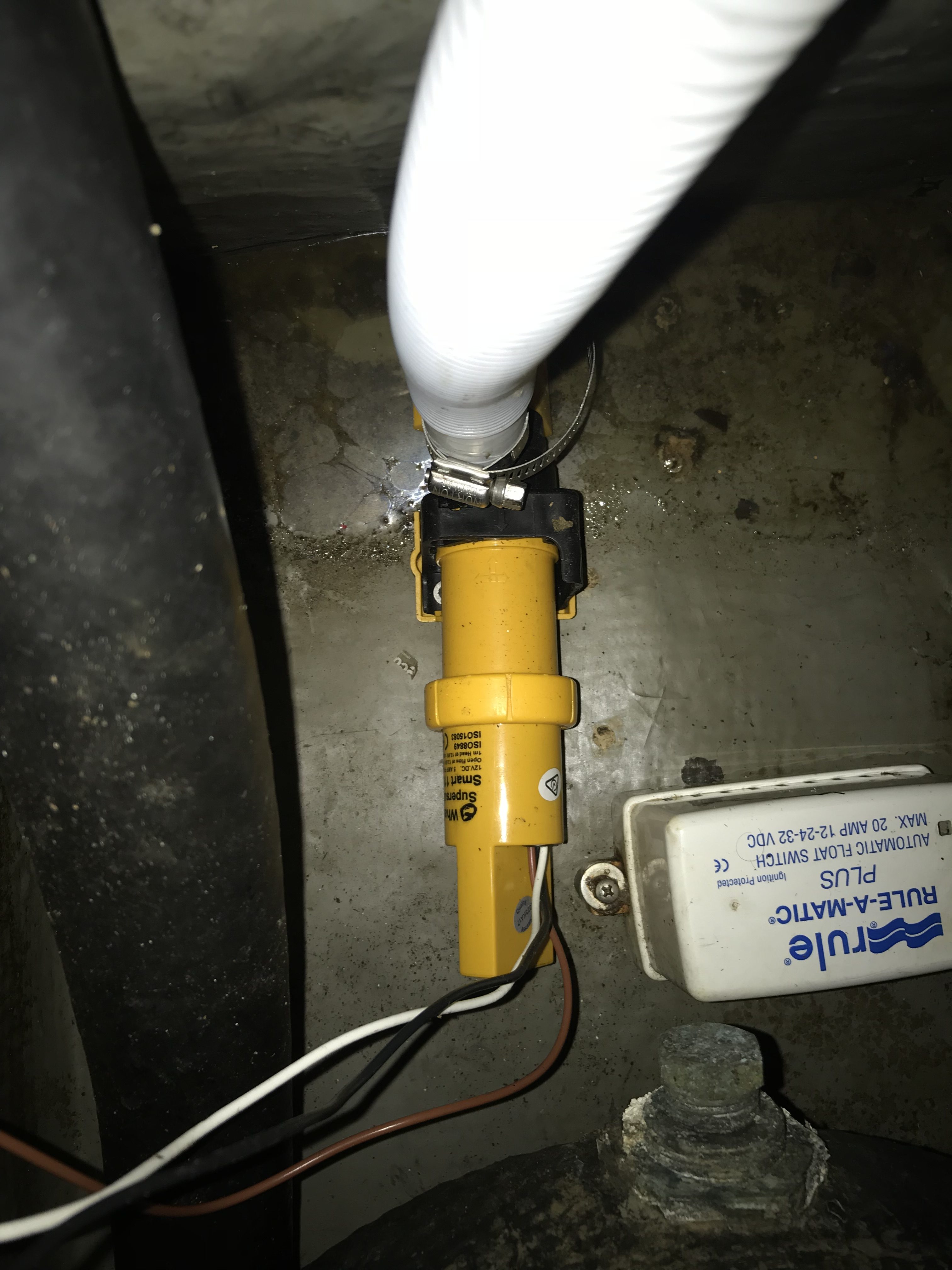 The new bilge pump
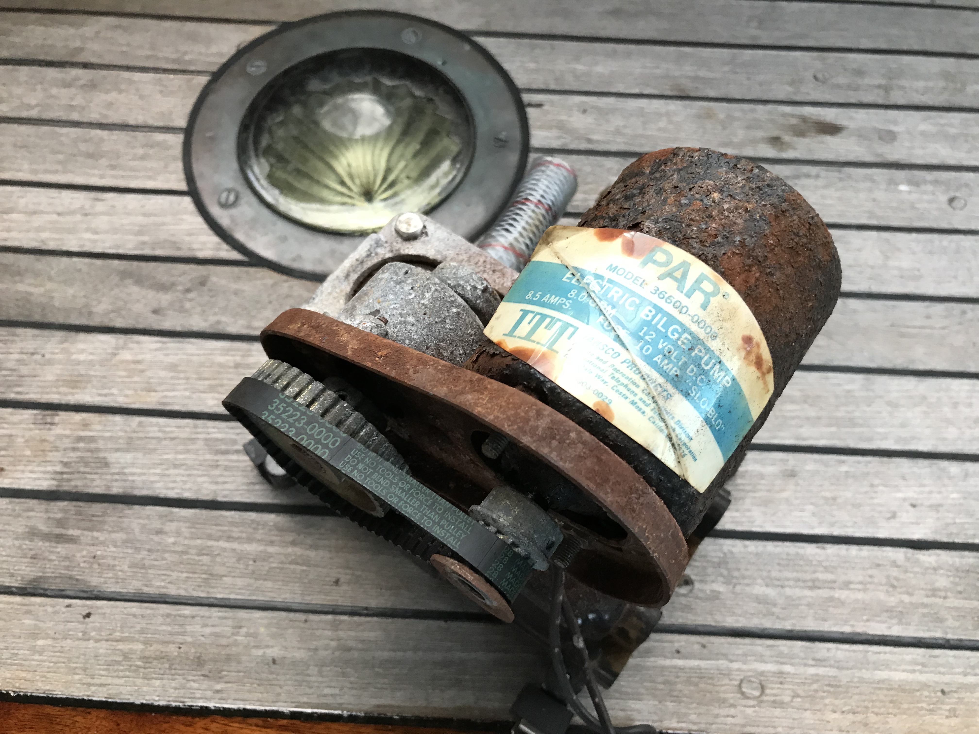 The old bilge pump
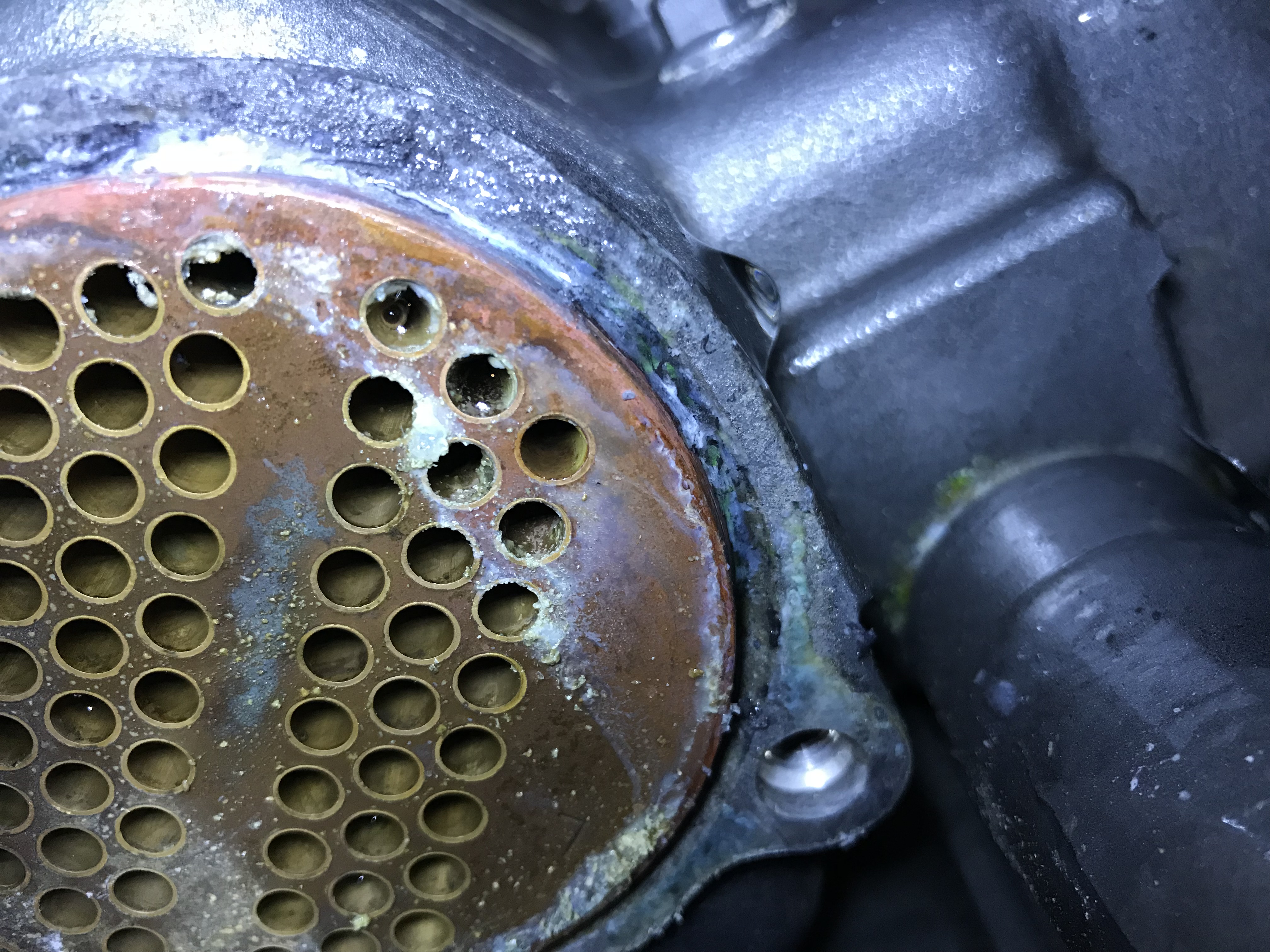
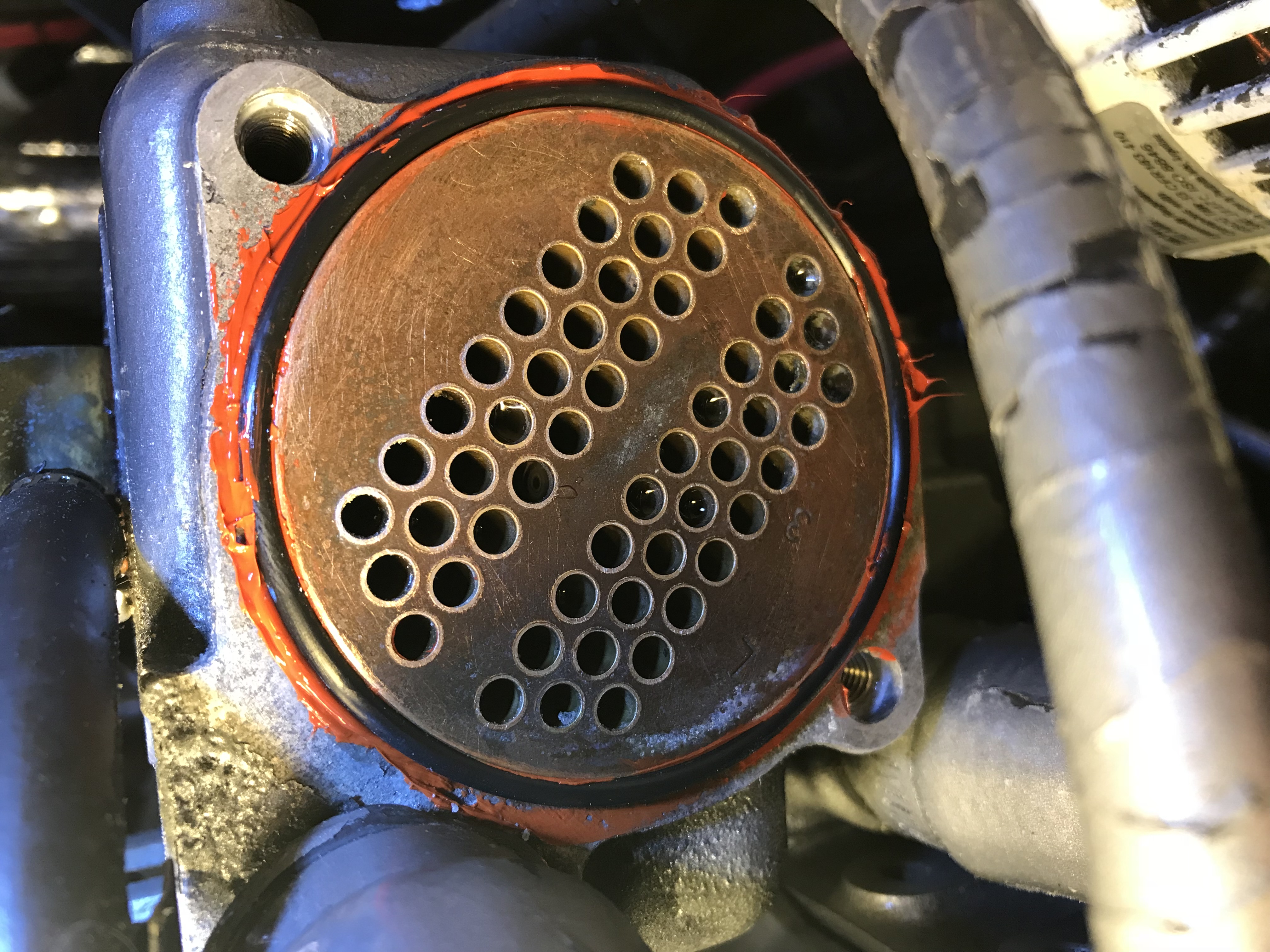
- Heat Exchanger–a marine diesel engine removes heat from the engine by passing sea water through a heat exchanger. The sea water passes through 54 copper tubes that are surrounded by fresh water (radiator fluid plus water) that circulates through the engine for cooling. Since saltwater runs through these tubes, they often get clogged and need to be removed for cleaning. The heat exchanger on my Yanmar engine sits on the side of the engine with not access, so removing it is challenging. The alternator needs to be swiveled away and some hoses need to be removed to gain access to the 2 end-caps. Once I removed the end-caps, I could shine a light through the tubes and found them to be surprisingly clean, with no buildup. This was probably due to the fact that since 2004 when the new engine was installed, the boat has lived in fresh water most of the time. Unfortunately I could not manage to slide the heat exchanger tube housing out of the heat exchanger, even tapping one end with a heavy mallet. I tried applying heat using a heat gun but there’s a lot of metal and it didn’t seem to get very warm. Since it looked very clean anyway, I decided to let well enough alone and not remove it. Using new O-rings, I reassembled the end-caps, turned the sea water valve back on, and water leaked from both end-caps. On my next attempt, I was more careful when seating the O-rings, and then I only had one end-cap leaking. But this was a different problem. I noticed the heat exchanger housing had corroded at the bottom lip of the end-cap. So as I tightened the end-cap bolts, the O-ring had nothing to push against so it wasn’t making a water-tight seal. I suspect there was a small leak that over time caused the metal housing to corrode. A new housing is around $2000, so I took a few days to think about how to fix it without buying a whole new heat exchanger. The O-ring is about 4″ in diameter, and the metal was corroded in only about 1/2″ of the outside groove. So I clipped a 1/2″ section out of the O-ring and seated the remaining O-ring (maybe now it’s a C-ring) in the end-cap groove. Then I applied high temperature gasket material where the 1/2″ gap was, hand tightened the end-cap bolts, let it sit for 1 hour, then fully tightened the bolts. After sitting for 24 hours, I opened the sea water valve and there was no leaks. I ran the engine for 30 minutes and still no leaks. I’ll keep an eye on it the next couple of times we take the boat out, but I think it’s a good fix.
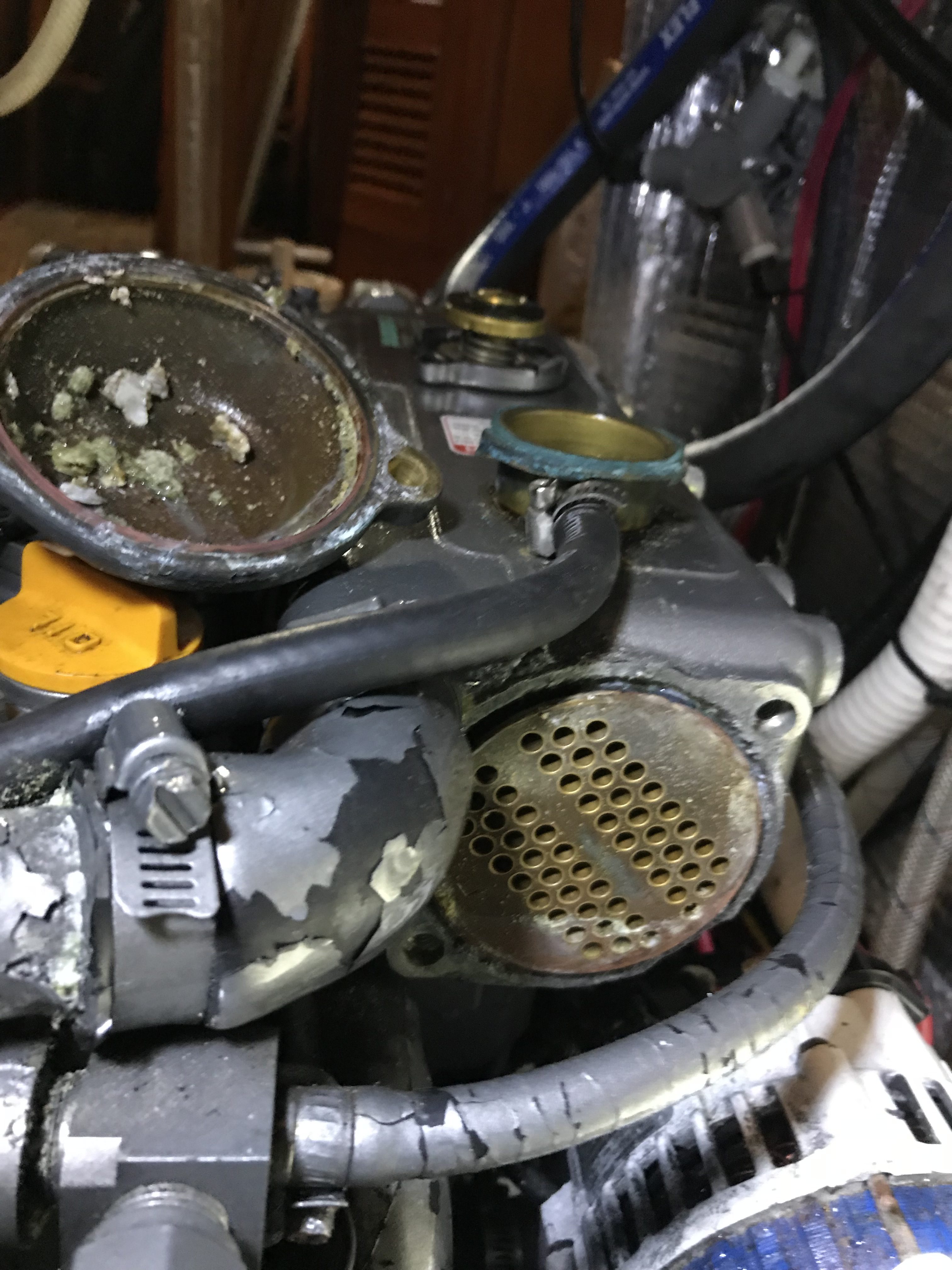 End-cap removed from heat exchanger
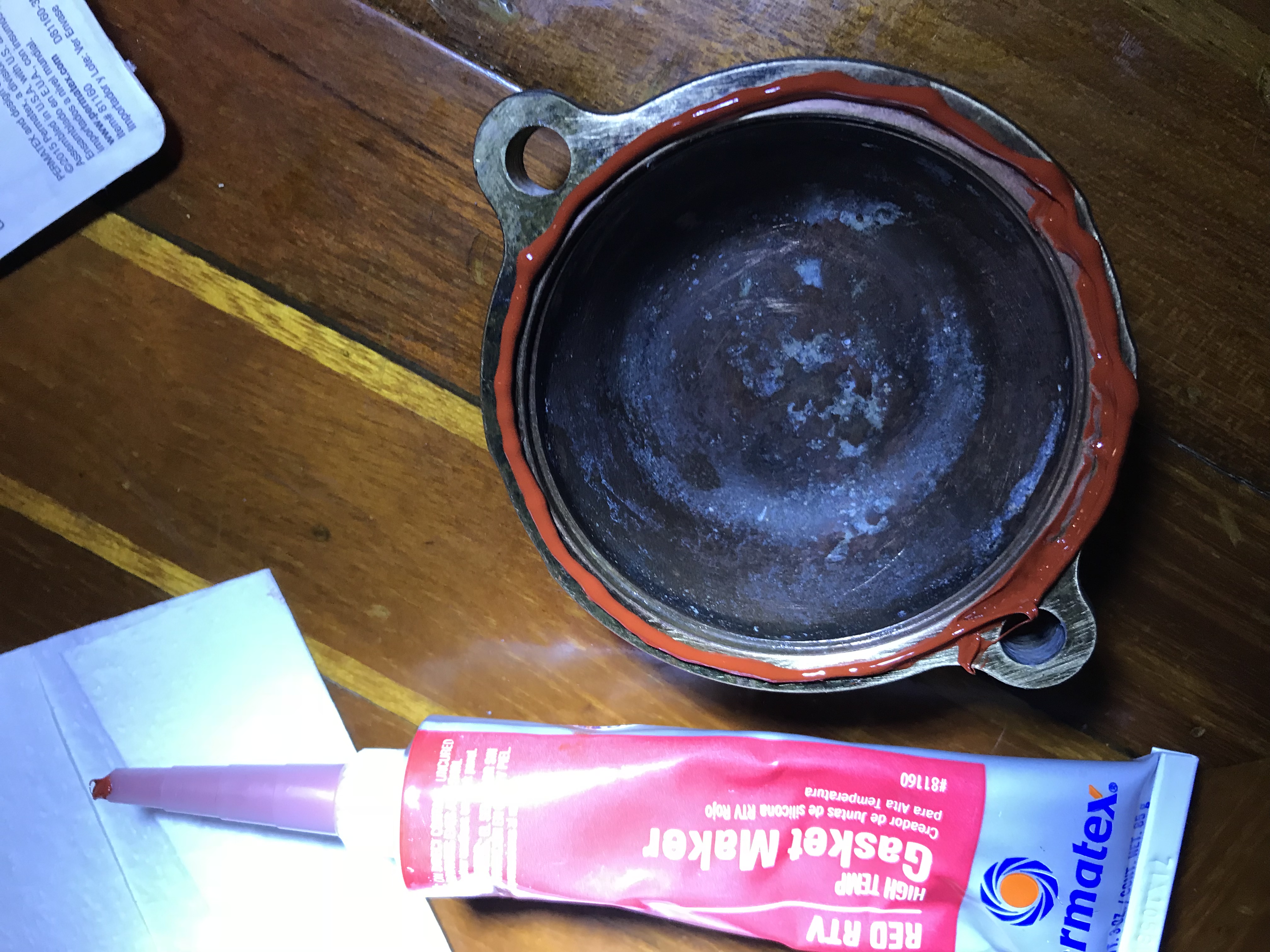 RTV Gasket Maker applied to end-cap
 After cleaning and applying gasket maker (this was before I cut the O-ring)
- Isolation Transformer–The marina recently upgraded its wiring to newer standards and throughout the winter, boats were tripping the more sensitive GFCI electronics. Eventually, the marina is requiring all boats to install isolation transformers. More common on boats in Europe, this is a safety device that helps prevent stray currents going into the marina water on boats that are not wired correctly or have a fault. Stray currents entering the water can cause muscles to cramp and result in electrocution and drowning of swimmers next to the boat. An isolation transformer magnetically isolates the shore AC power from the boat AC power. So it also protects a boat from faulty marina wiring. I decided to buy a Charles Industry “international” 3.5KVA transformer. The international part means that it can be configured to accept either 120VAC or 240VAC shore power, and output either 120/240VAC. So I could (theoretically) take the boat to Australia and, after moving a few jumpers to reconfigure the isolation transformer, plug into a 240VAC dock power and have 120VAC onboard. The transformer weighs a whopping 70 lbs with its iron core and windings. I used the space from where I removed the old bilge pump to install it–it’s a dry place and sits directly below the AC electrical panel. Since it didn’t quite fit, I had to saw a small piece off the bottom mounting bracket, then drill 4 holes and screw it down. Next I made the 4 required jumpers to configure it for 120VAC input and 120VAC output using 12 gauge wire. Next I ran new 3-strand 8 gauge wire from the shore input connector to the isolation transformer. The run was only 10 feet long but it took about half a day! There a 4′ section that you can’t see or feel, but the wire would not push through. 3-strand 8 gauge wire is pretty thick, so I ended up removing the sheathing and feeding each wire (hot, neutral, ground) through separately. I suppose I could have used the existing wire, but it wasn’t long enough to reach the transformer and I didn’t want any connectors. Plus I wanted all new wiring for such an important piece of equipment. Next I had to figure out how to wire the output of the transformer. I made a complete diagram of the boat’s AC electrical system, then researched (Nigel Calder’s electrical book, Google searches) and came up with a plan. I learned that without an isolation transformer, it’s important to never short AC neutral (white) to ground (green). This is done on shore at the marina. But with an isolation transformer, you must short the neutral and ground on the boat. I also learned exactly what the AC Main dpdt switch does, and what the SHORE/OFF/INVERTER switch does. In short, I learned a lot about the AC system on my boat. After wiring up the output hot/neutral/gnd, and swapping the new wires into the shore power input connector, I nervously turned the power on and it worked. Before installing the isolation transformer, when plugging into the shore power, I had to bring things up in a particular way or else I would trip the sensitive marina electronics (it has to so with the boat inverter powering up with a 30 second short between neutral to ground). With the isolation transformer, I no longer need to delay the SHORE/OFF/INVERTER switch 30 seconds. The final step was zip-tying and labeling the new wiring. The isolation transformer and all the wiring and connectors was about $1000. Project time was about a month.
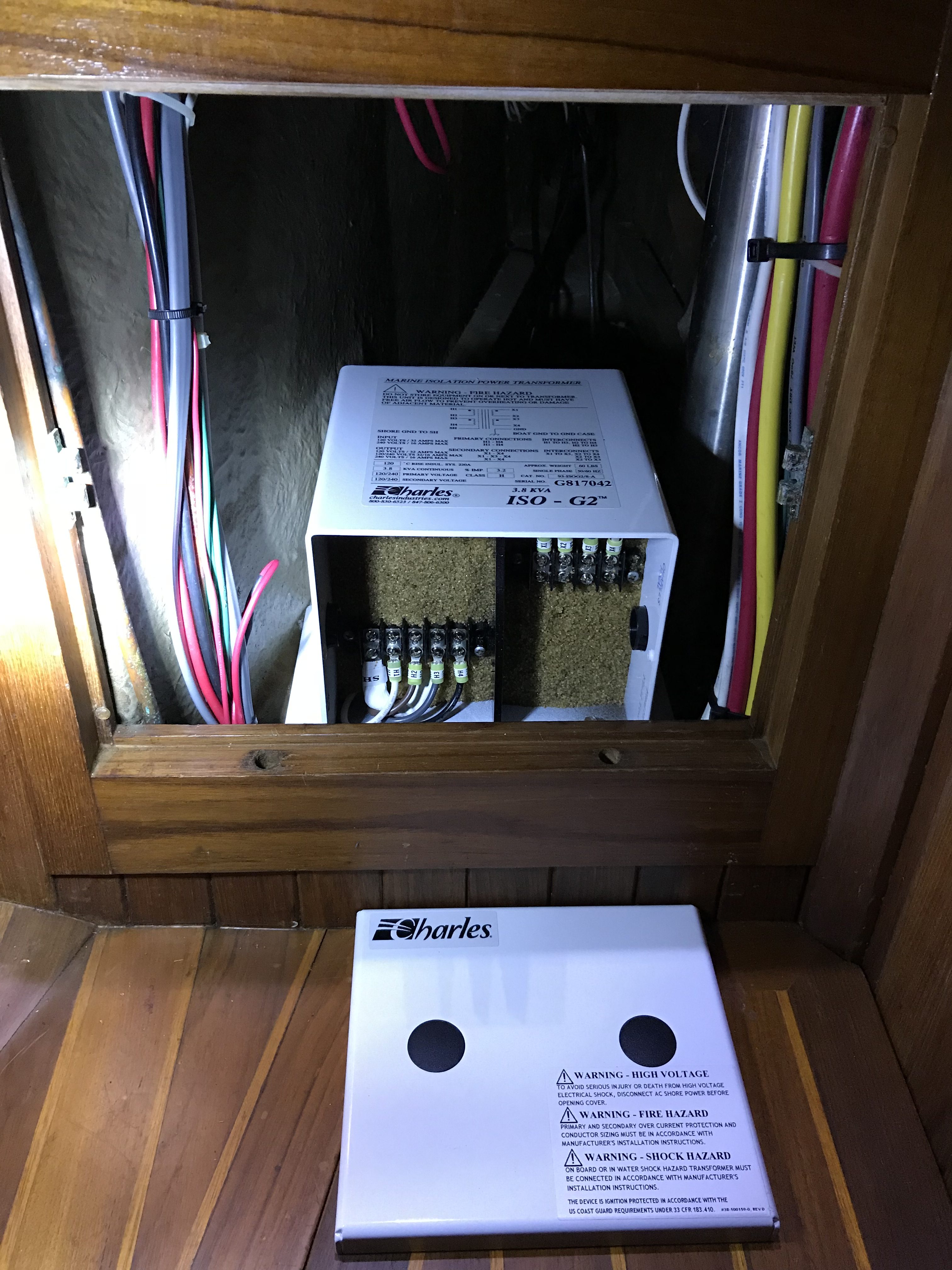 Installation location with easy access
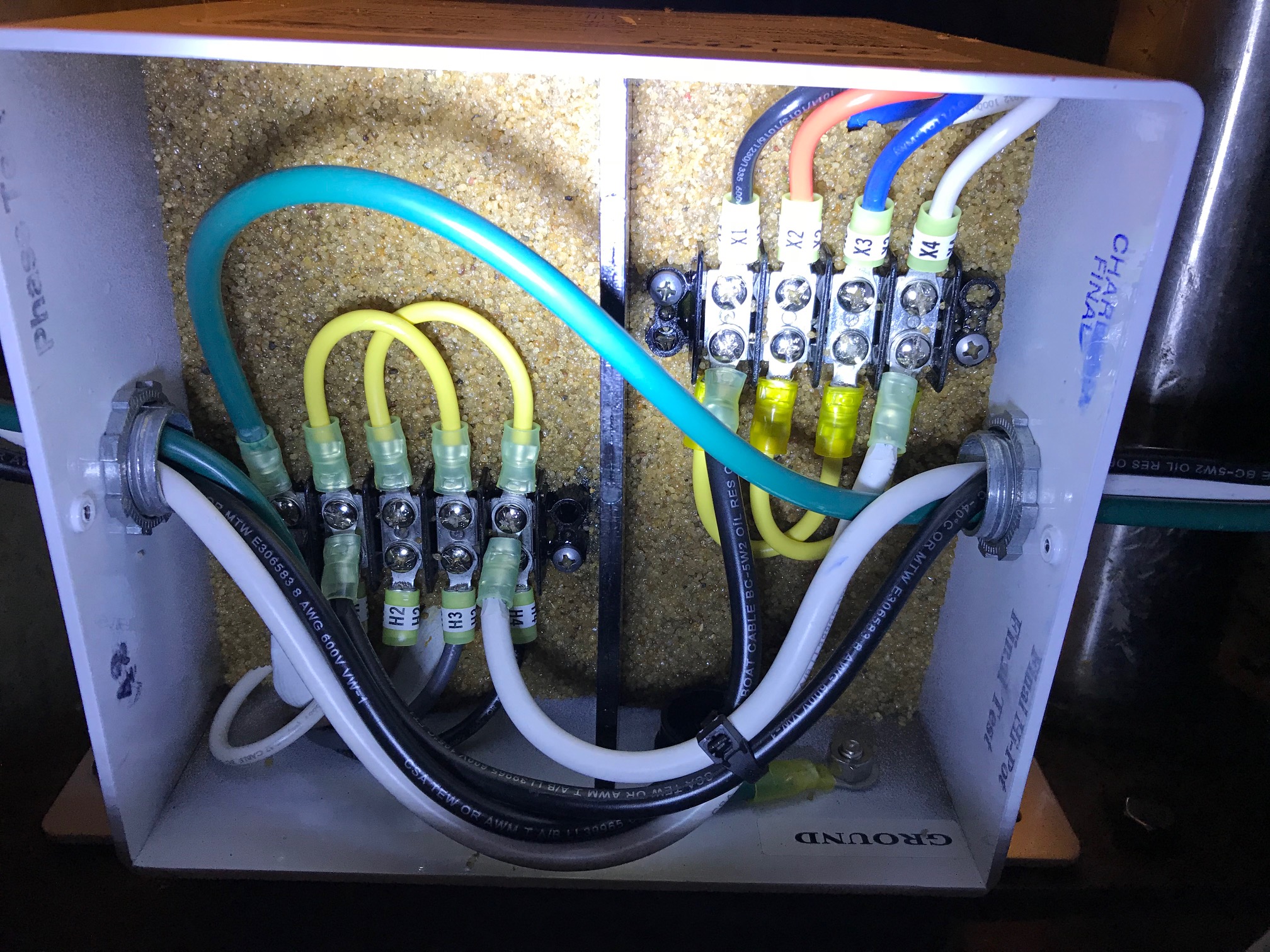 Wiring inside isolation transformer
Here’s a diagram showing the complete AC System of the boat: AC System Diagram
Here’s a diagram showing the complete DC System of the boat: DC System Diagram
Hydraulic Pressure Gauge–By the end of the trip, corrosion got the best of various metal items. This is what the hydraulic pressure gauge looked like (top) and the new gauge I mounted to the hydraulic fill cylinder. Cost was $15.
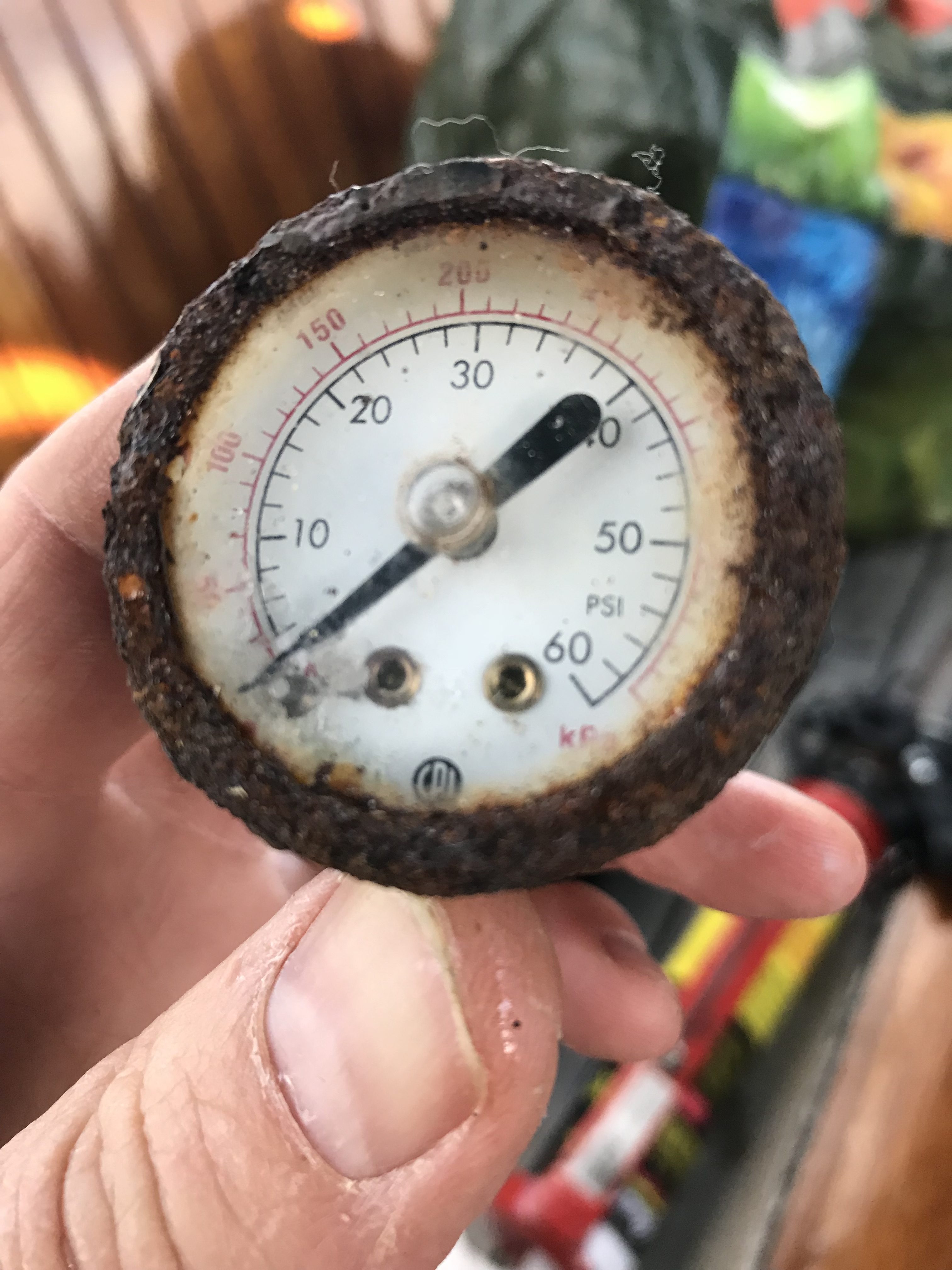 Old pressure gauge
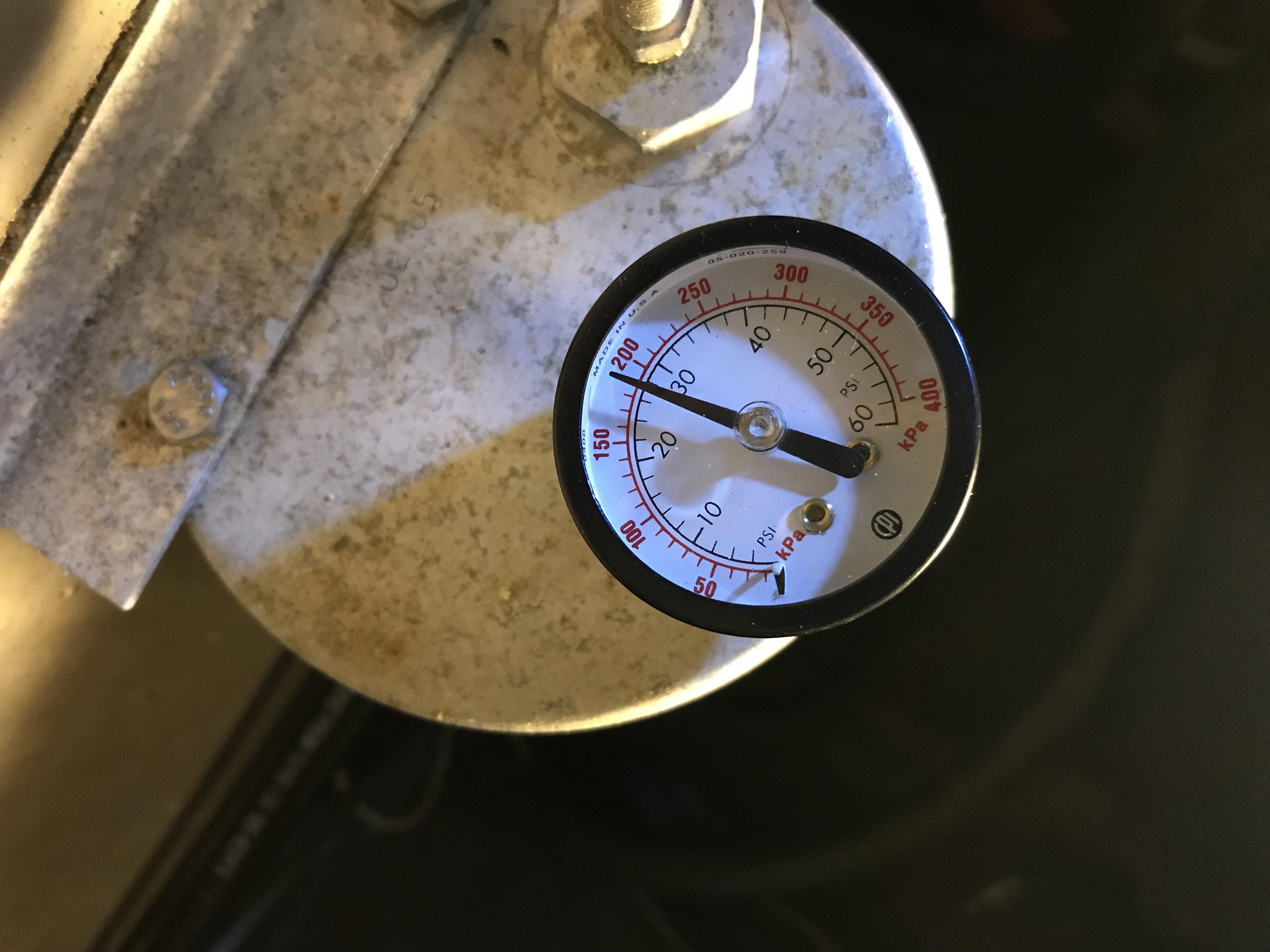 New pressure gauge
