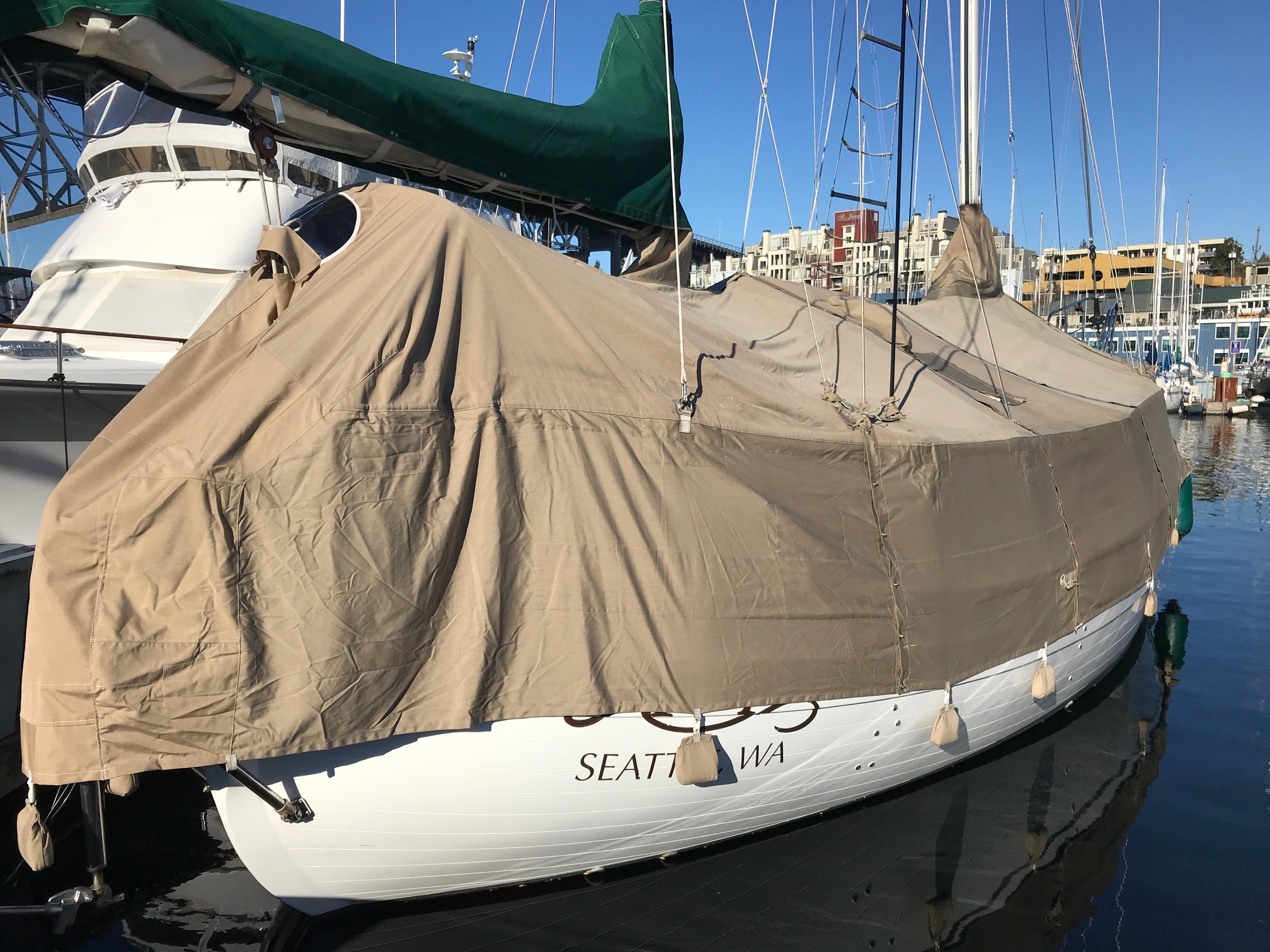
I had a full boat cover made around 10 years ago. I normally put it on in November and take it off in April, so it gets used 5 or 6 months a year. The cover was made of heavy duty Sunbrella canvas, and was built in 4 sections that zipper together and keep Apropos almost completely dry from stem to stern during Seattle’s rainy season. With cutouts for 2 masts and 11 stays, I was amazed at how well it was built by The Canvas Company located in Seattle.
About 5 years ago, to make room for a bimini, I raised the mizzen boom 13″. Since the aft section of the cover went over the mizzen boom, that section no longer fit. For the past couple of years I didn’t use the aft section and just relied on the bimini with full enclosure of the cockpit to keep the aft 1/4th of the boat “dry”. But a lot of the brightwork was outboard of the cockpit enclosure, so I decided to have the aft section of the cover modified so that it could be used.
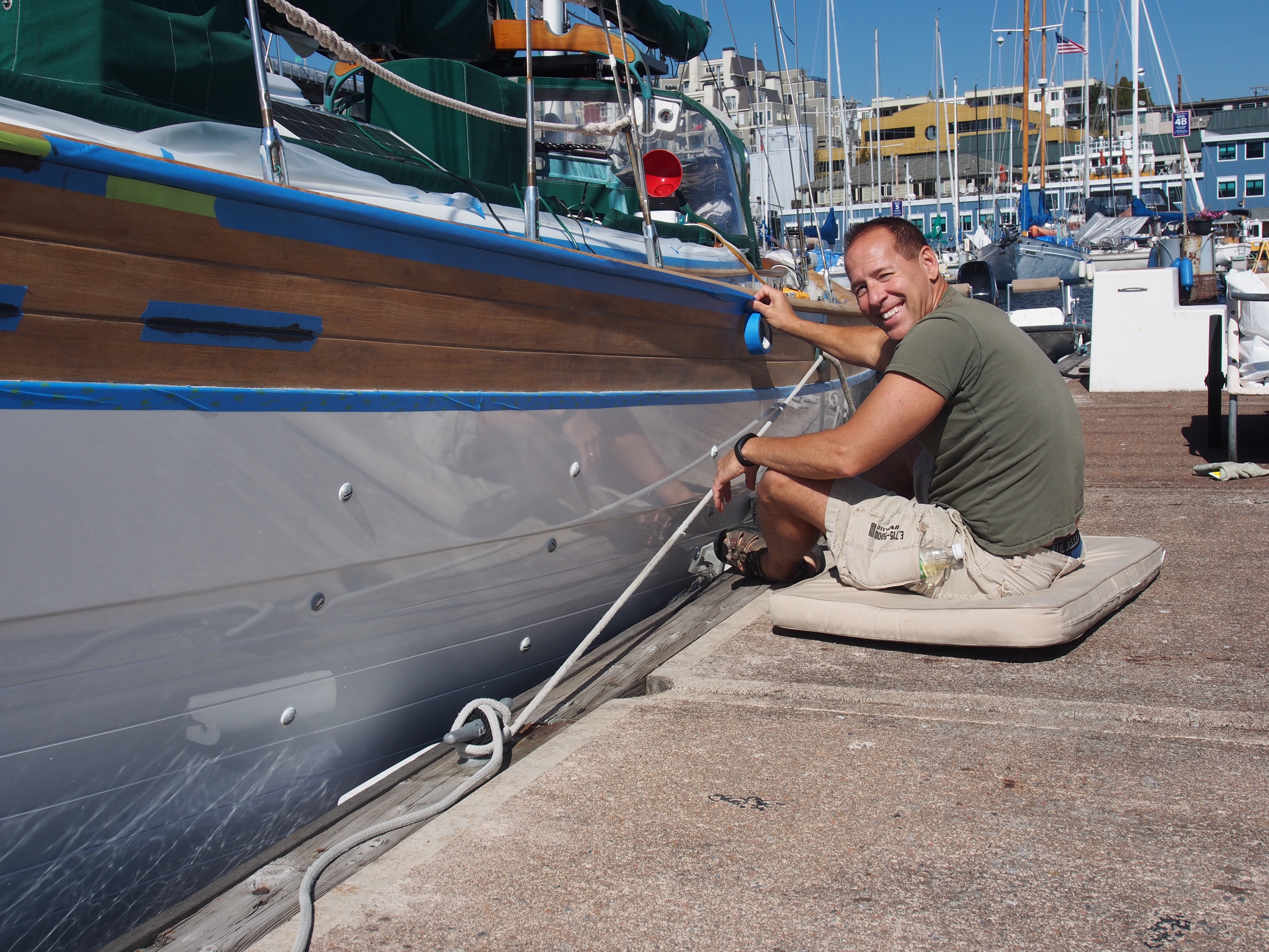
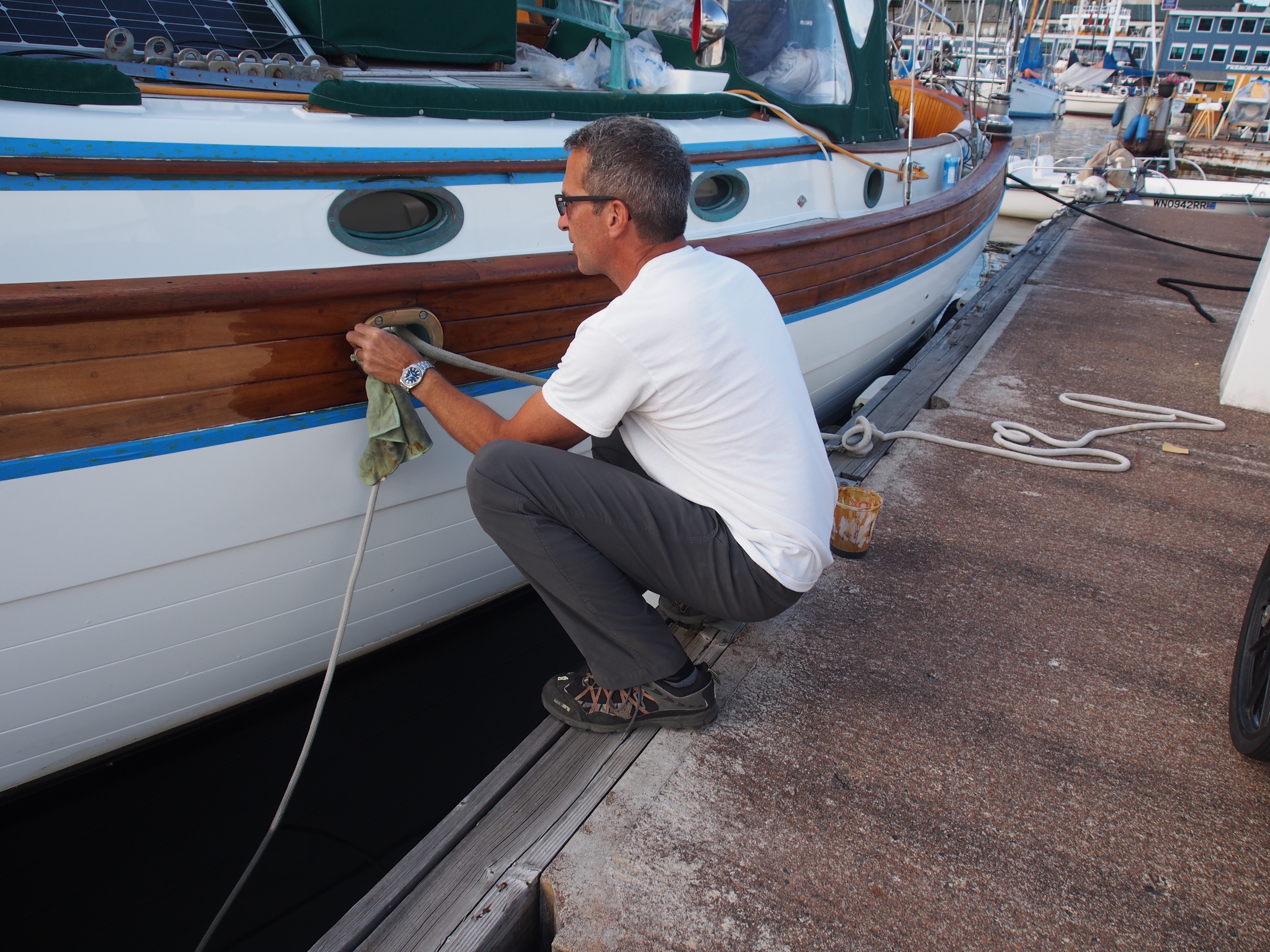
After getting a quote for over $2000 to modify the cover, I did what any good sailor with a Sailrite machine would do–make it a DIY project!
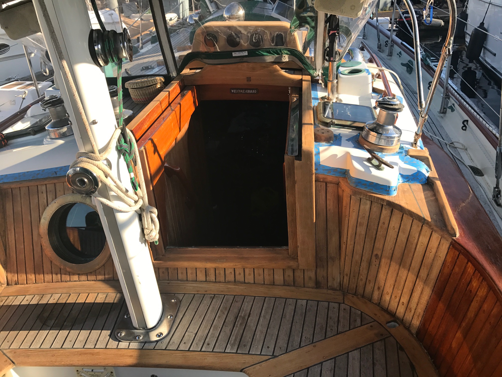
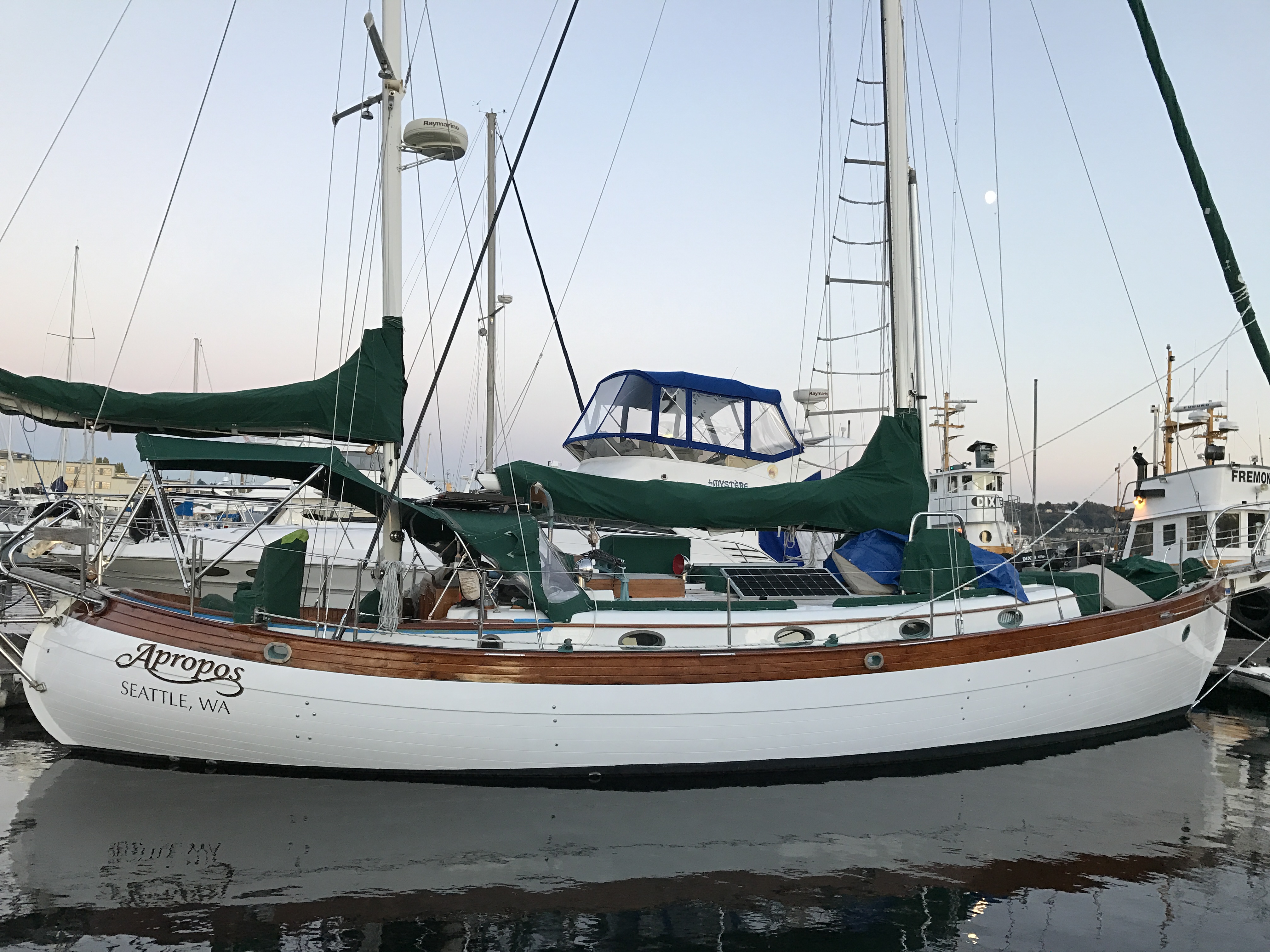
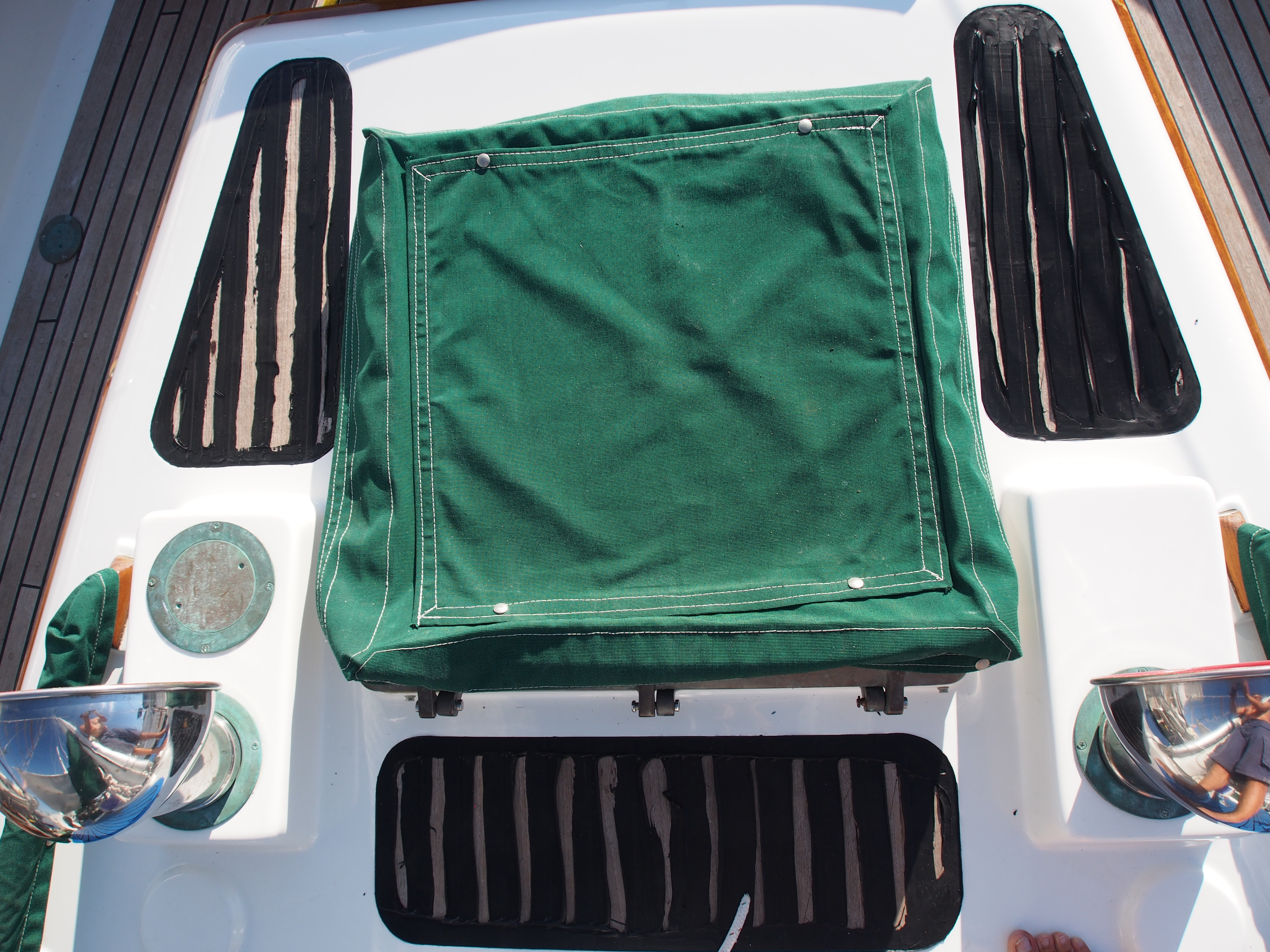
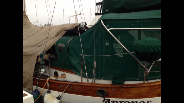
Here is a picture showing how the cover was used without the aft section:
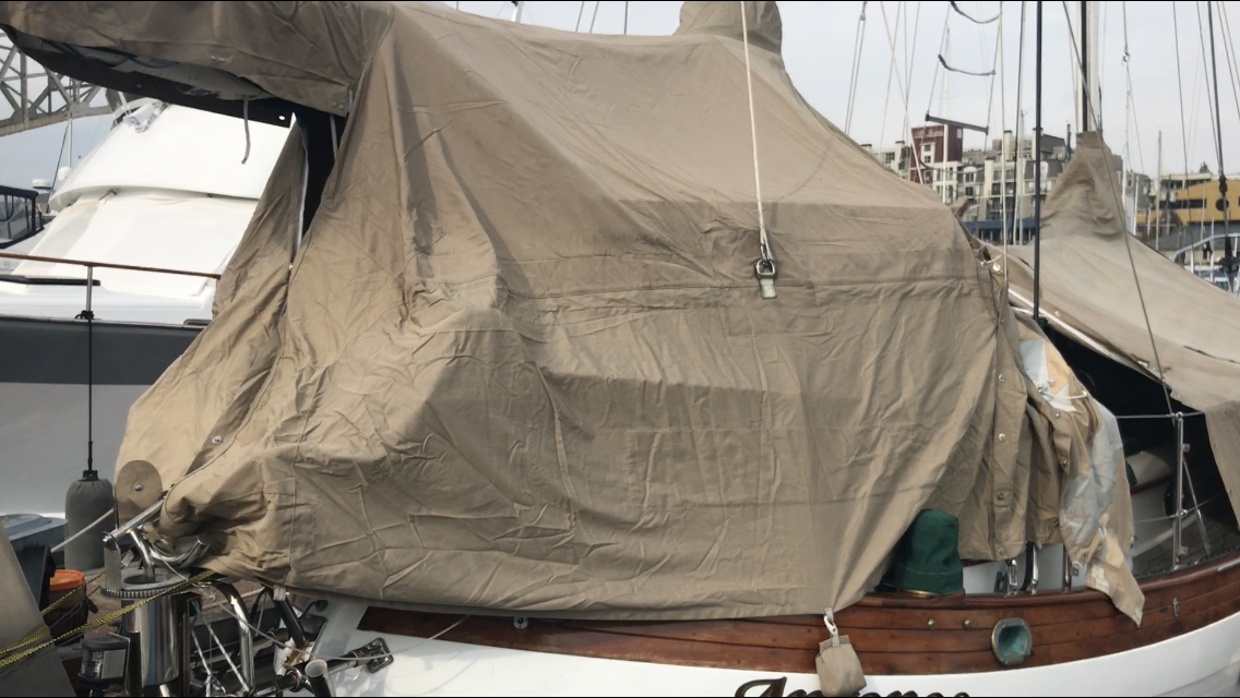
Next is a picture showing how it looked trying to hang it over the mizzen boom that had been raised 13″ (it hung way too high, didn’t reach the forward section, and didn’t cover the wind vane):
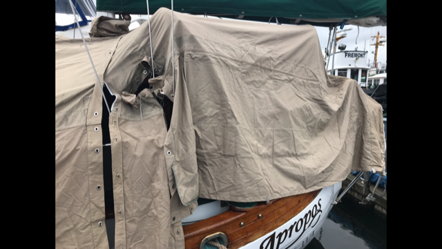
Next we tried hanging it below the boom but over the bimini (although it reached the forward section, it still fit too high and the openings for the stays were way off):
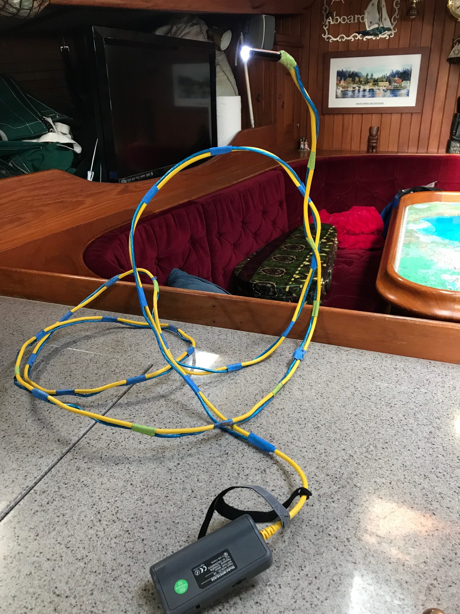
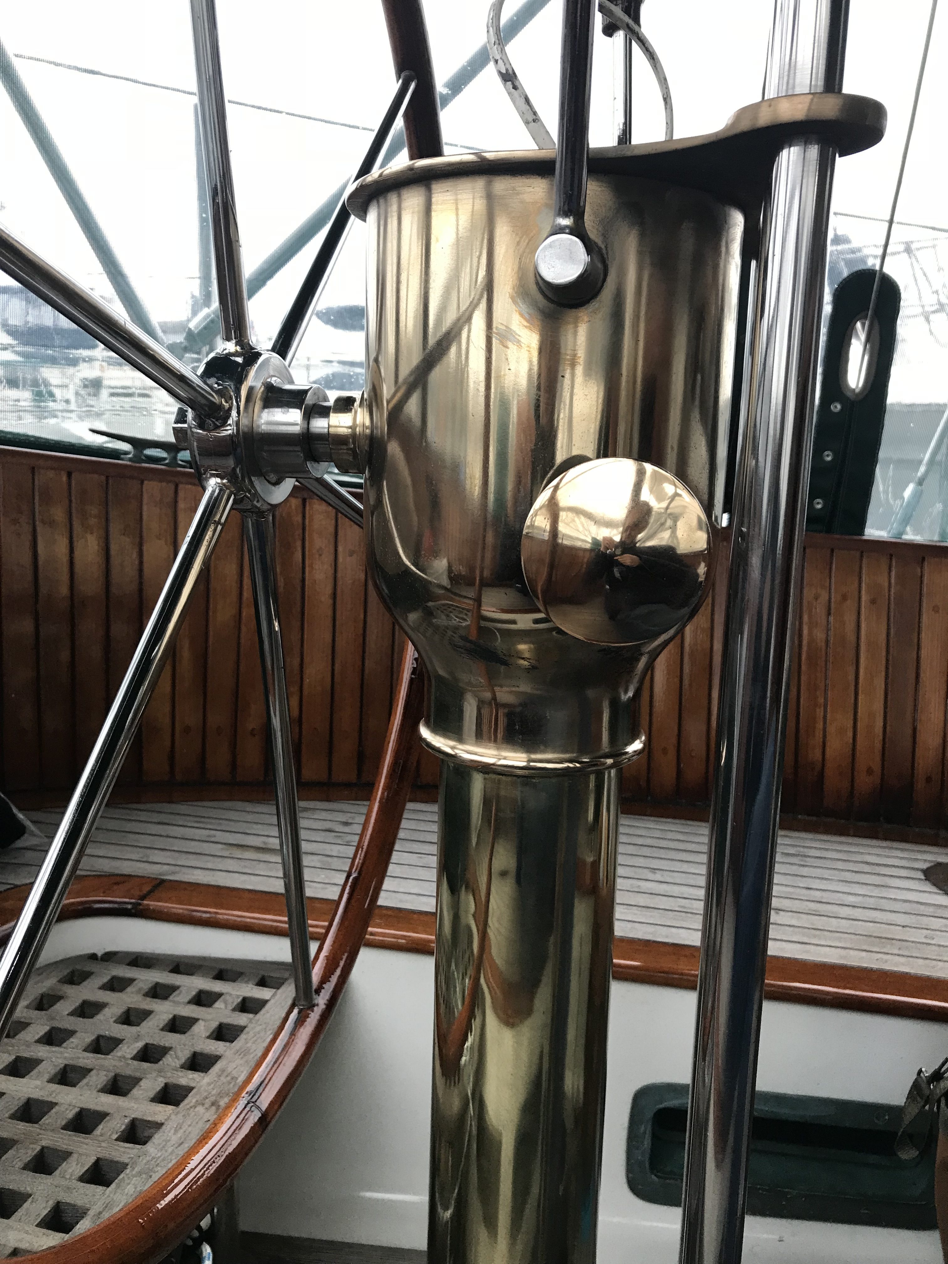
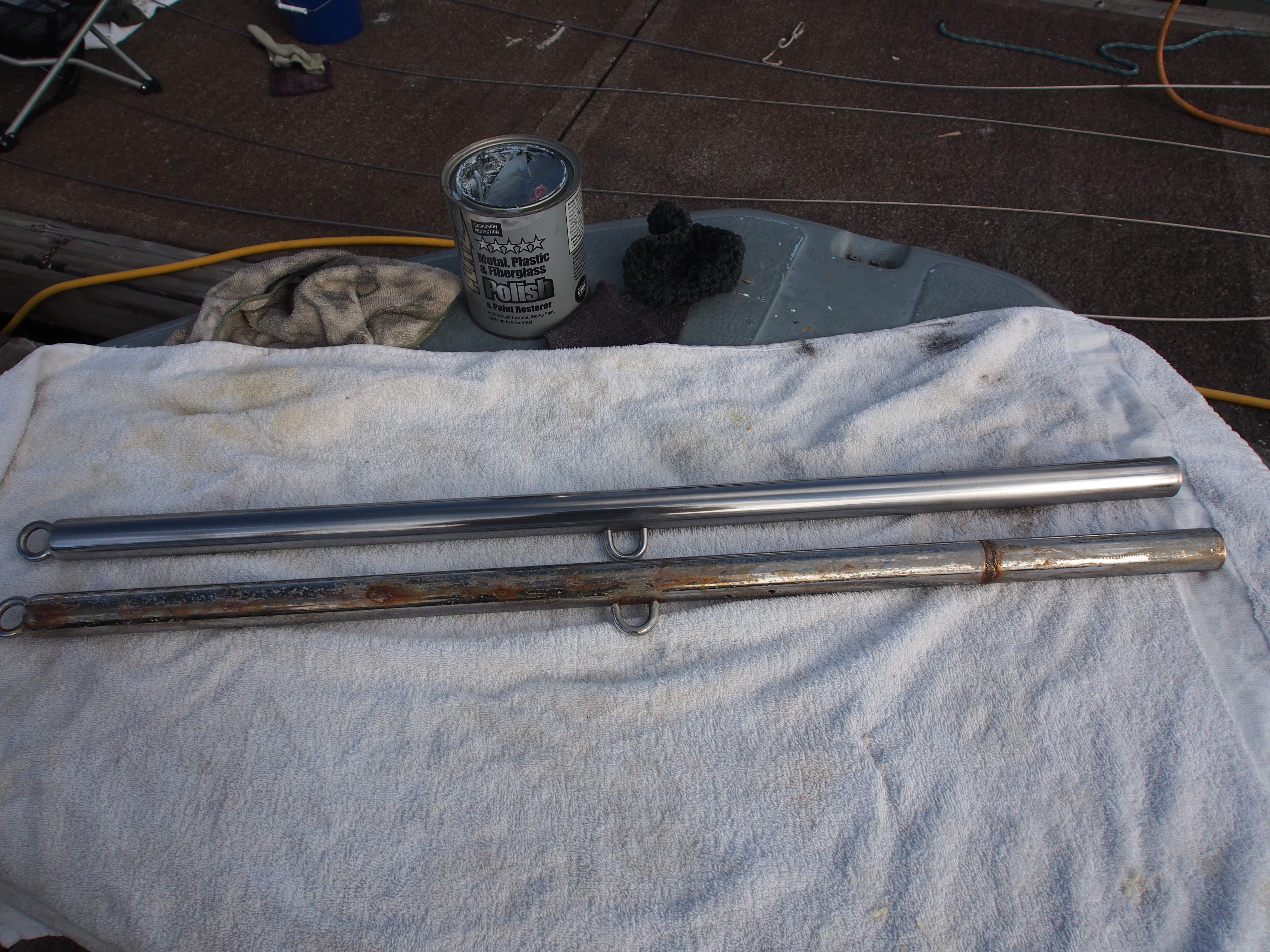
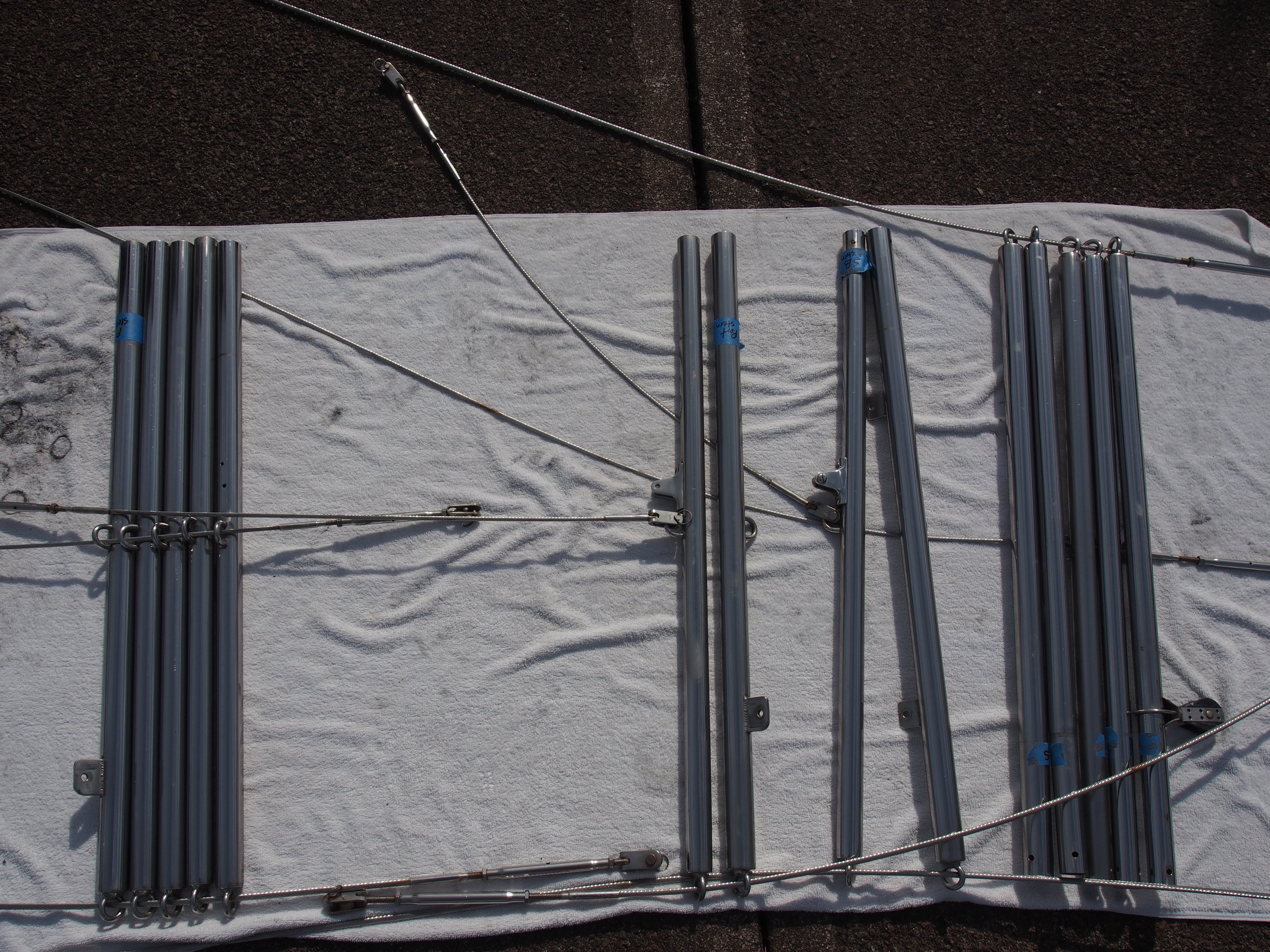
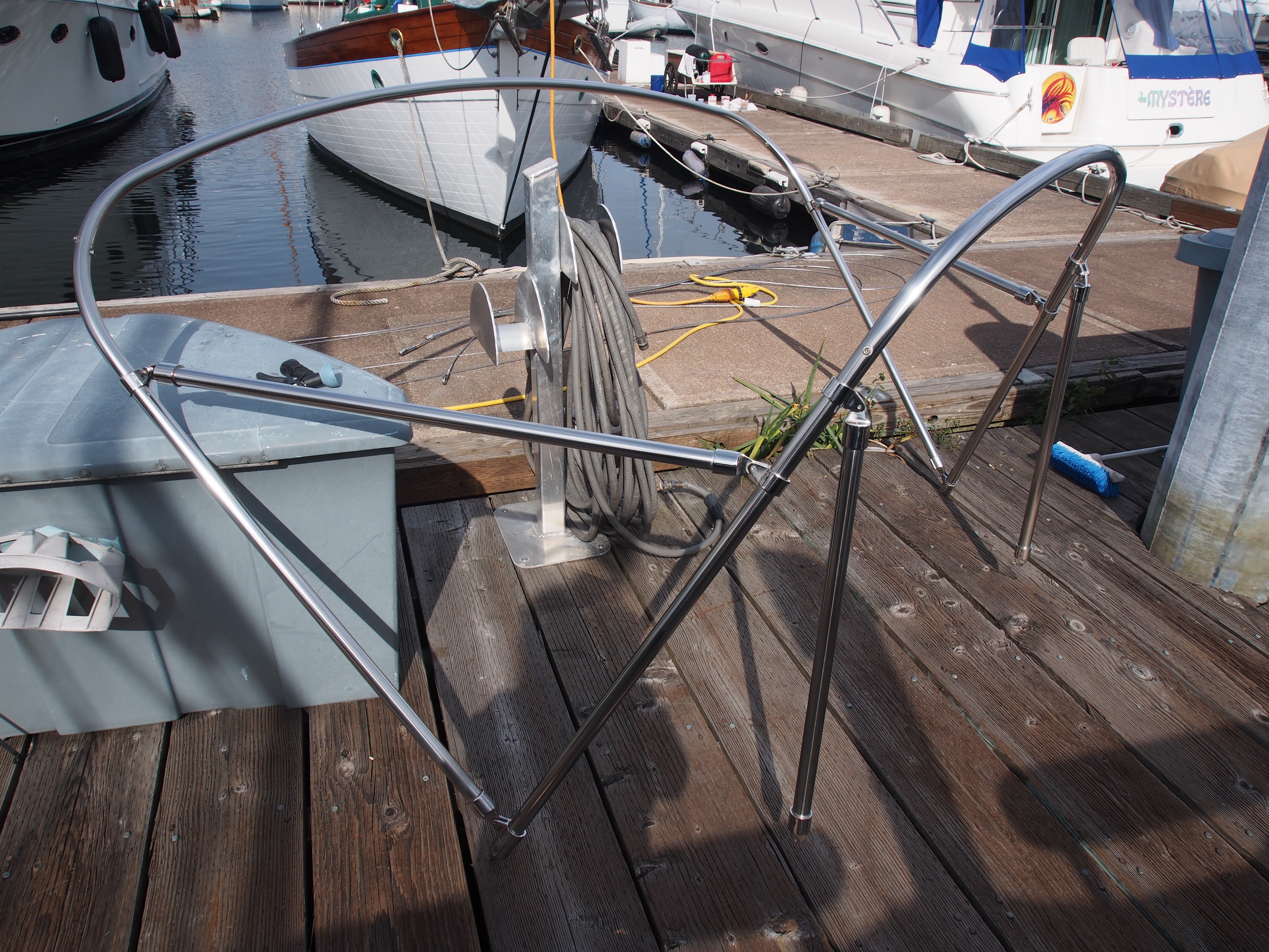
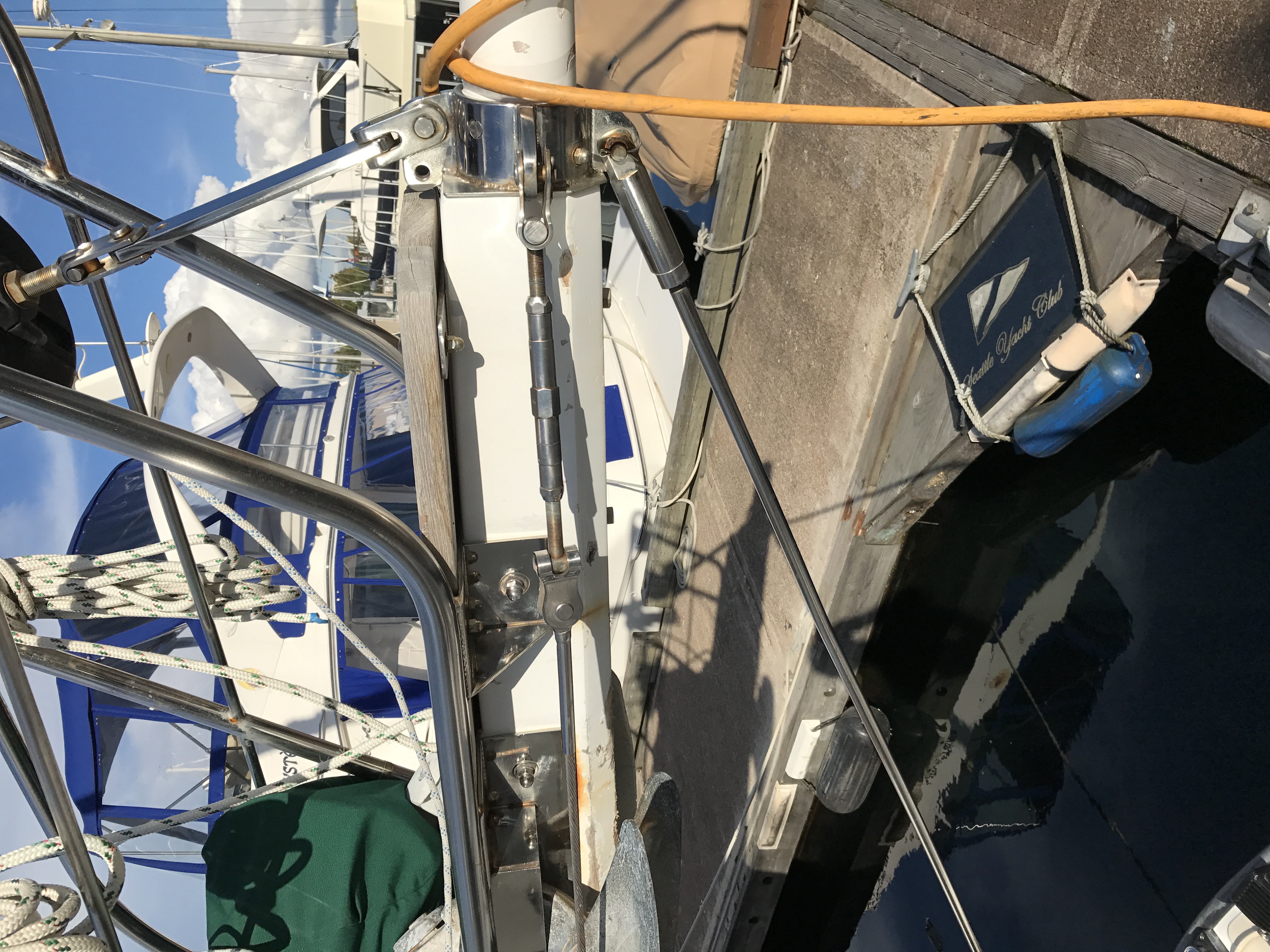
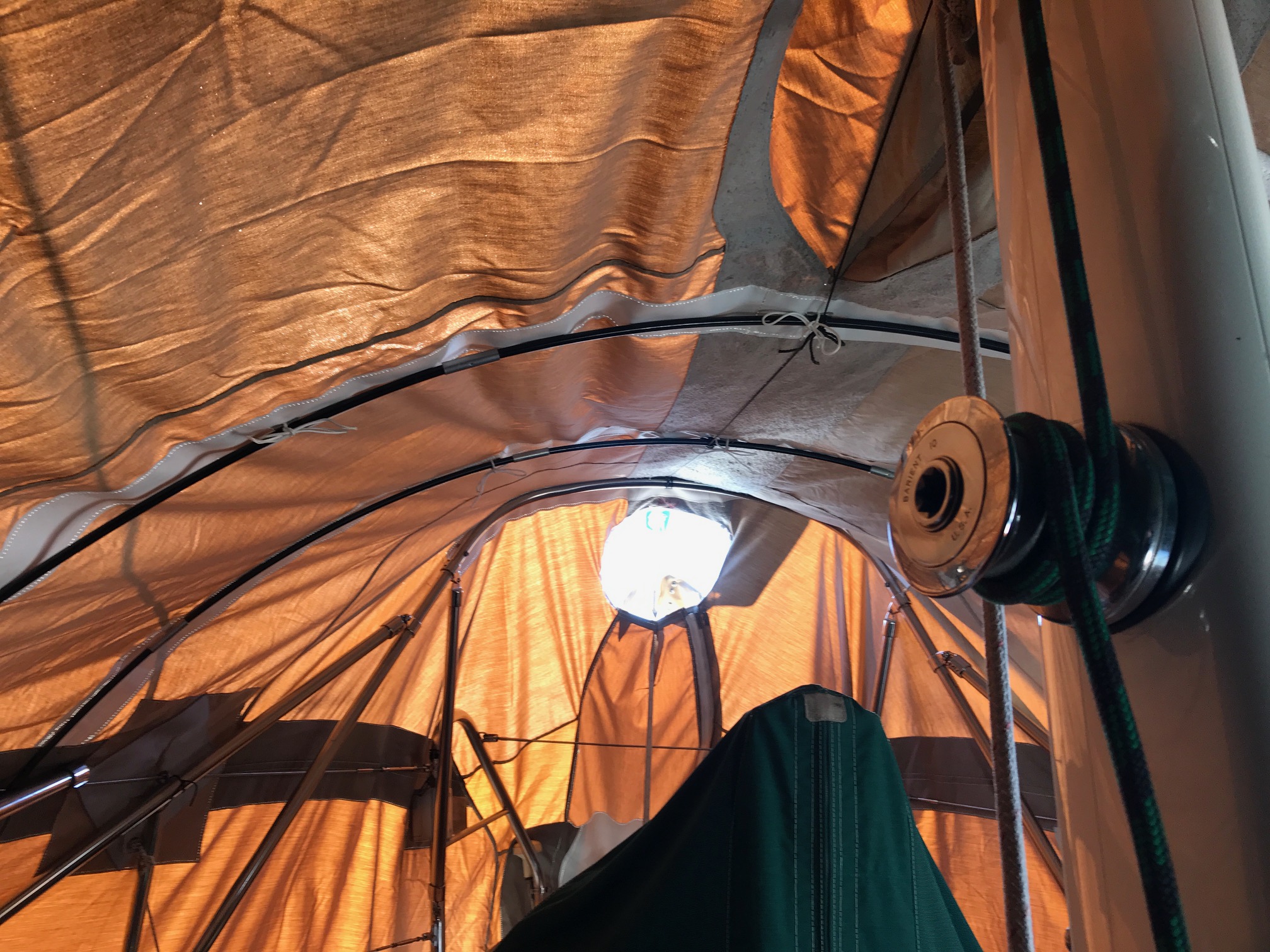
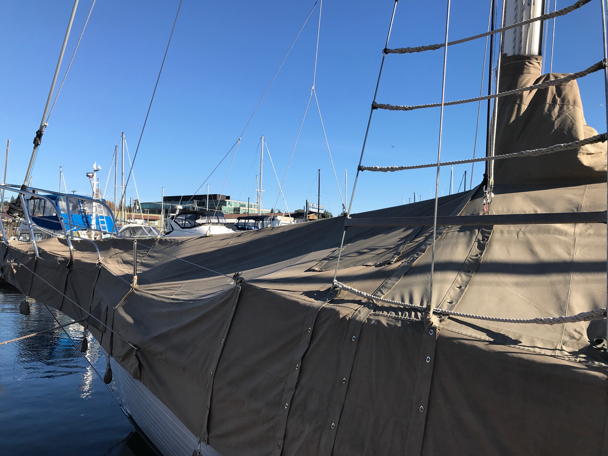
It would have taken a lot of work to modify the cover to fit in the position shown above. After some more thinking, we decided to remove the bimini canvas and the forward section of the bimini frame. This allowed the cover to sit perfectly to mate up with the forward section and all the stays. In order to cover the windvane, I added a panel to the aft end. I used 2 fiberglass tent poles to help support the cover (they can be seen in the picture taken of the inside). Here are some final pictures of the fit after all the modifications were done:
In order to get the above fit, we made the following modifications:
- removed the seam on the aft end and added a 14″ section to allow it to completely cover the wind vane (this required moving one side of the zipper and the outside flap that covers the zipper)
- sewed in white vinyl protective material wherever the inside of the cover touched the bimini frame, the 2 tent poles, and dodger side rails, and the solar panel atop the dodger
- removed the boom cover section (the boom extension cover used originally when the cover sat over the mizzen boom) and replaced with a vinyl window to allow light in and also to see out
Overall, I’m happy with the fit of the boat cover now. The downside is I will have to remove the bimini canvas and part of the bimini frame whenever I put the cover on, but this only takes 10 minutes. The only cost of the project was about $50 for Sunbrella canvas and $30 for vinyl material called Shelter-Rite…. (vs $2000 for a complete retrofit of the aft cover section to make it fit over the boom). Total time spent ripping out seams, sewing, and trial fitting was around 30 hours.
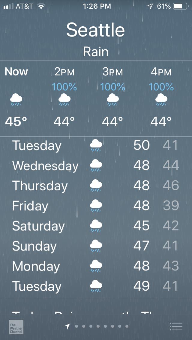
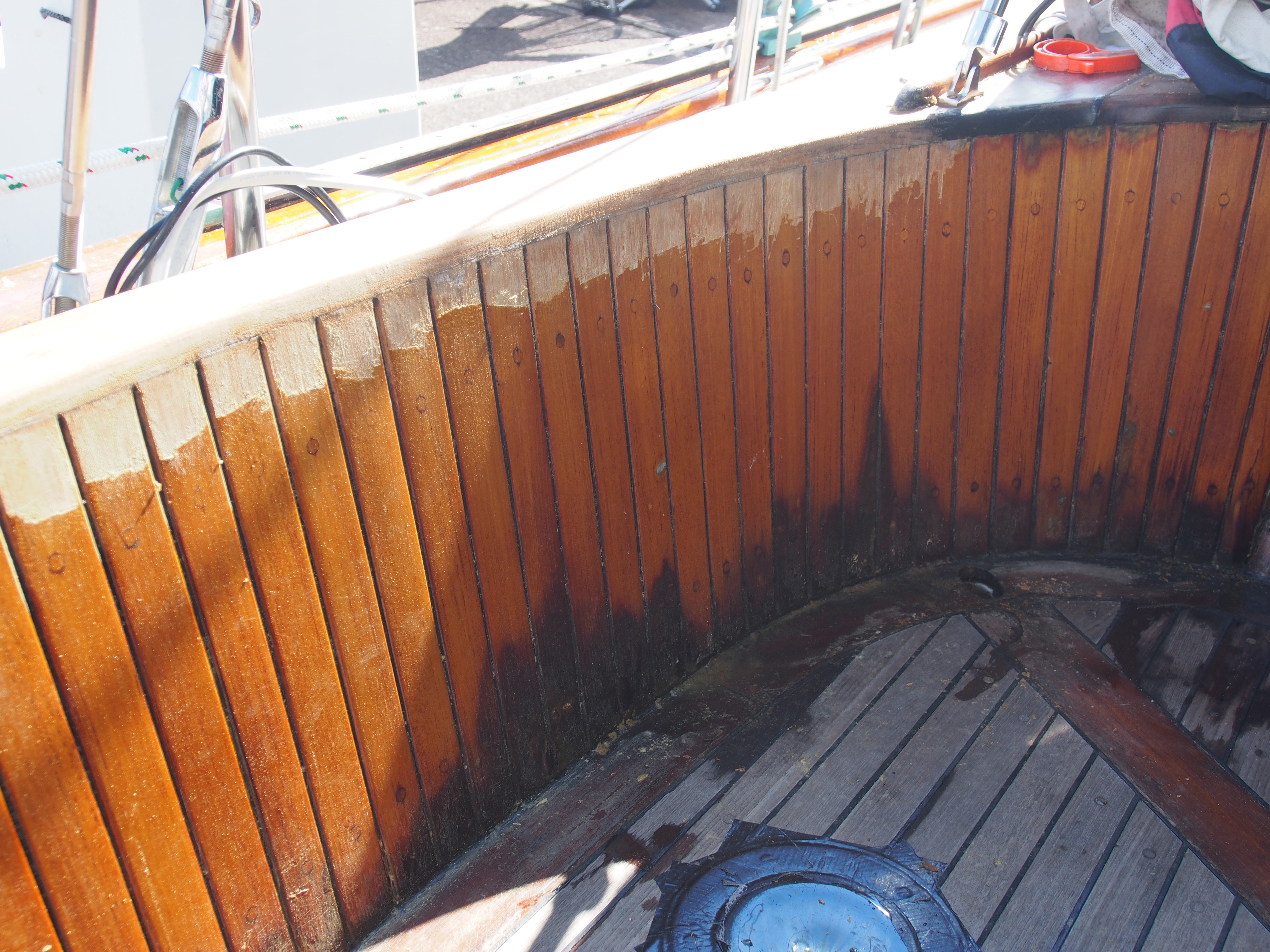
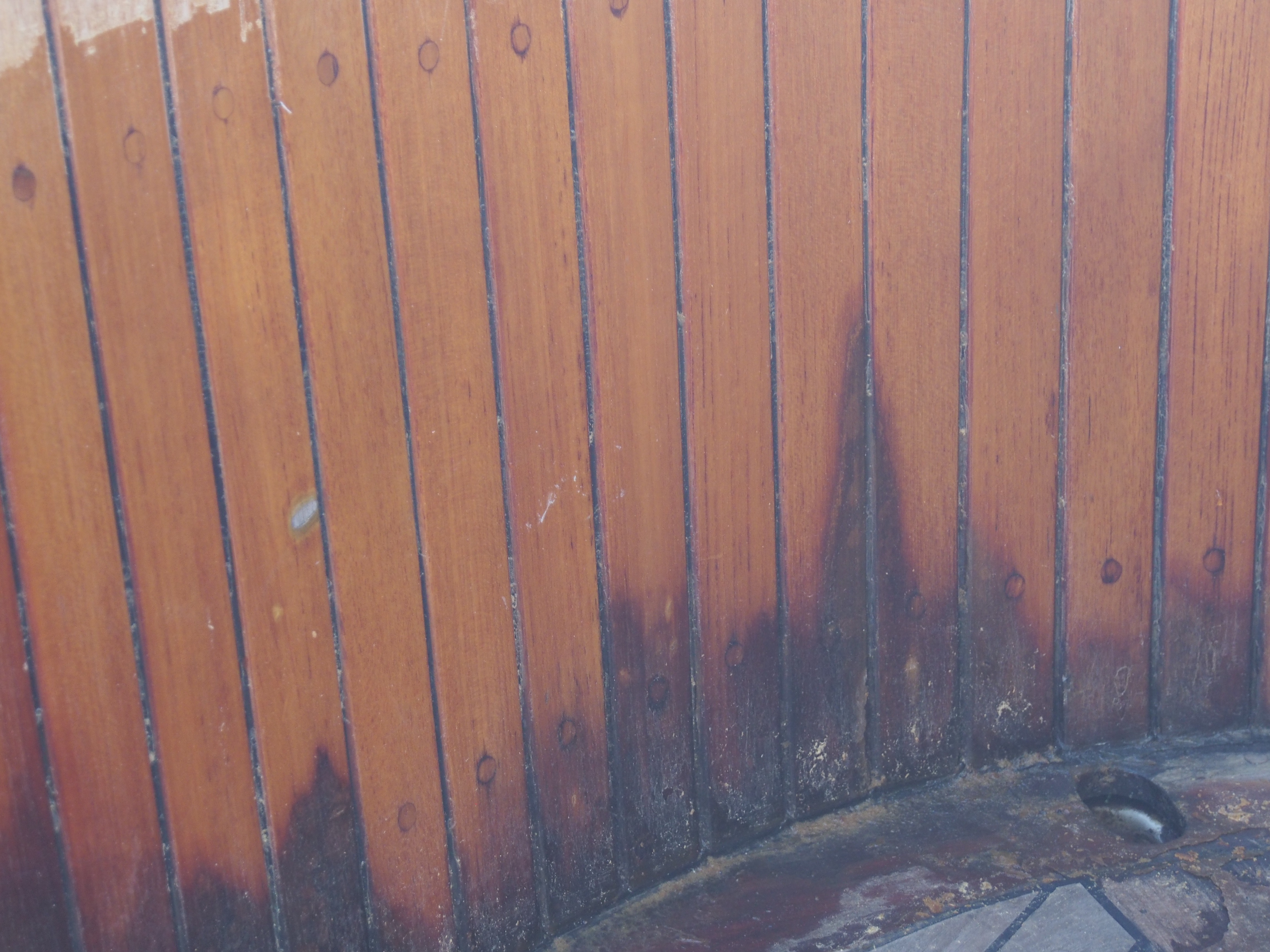
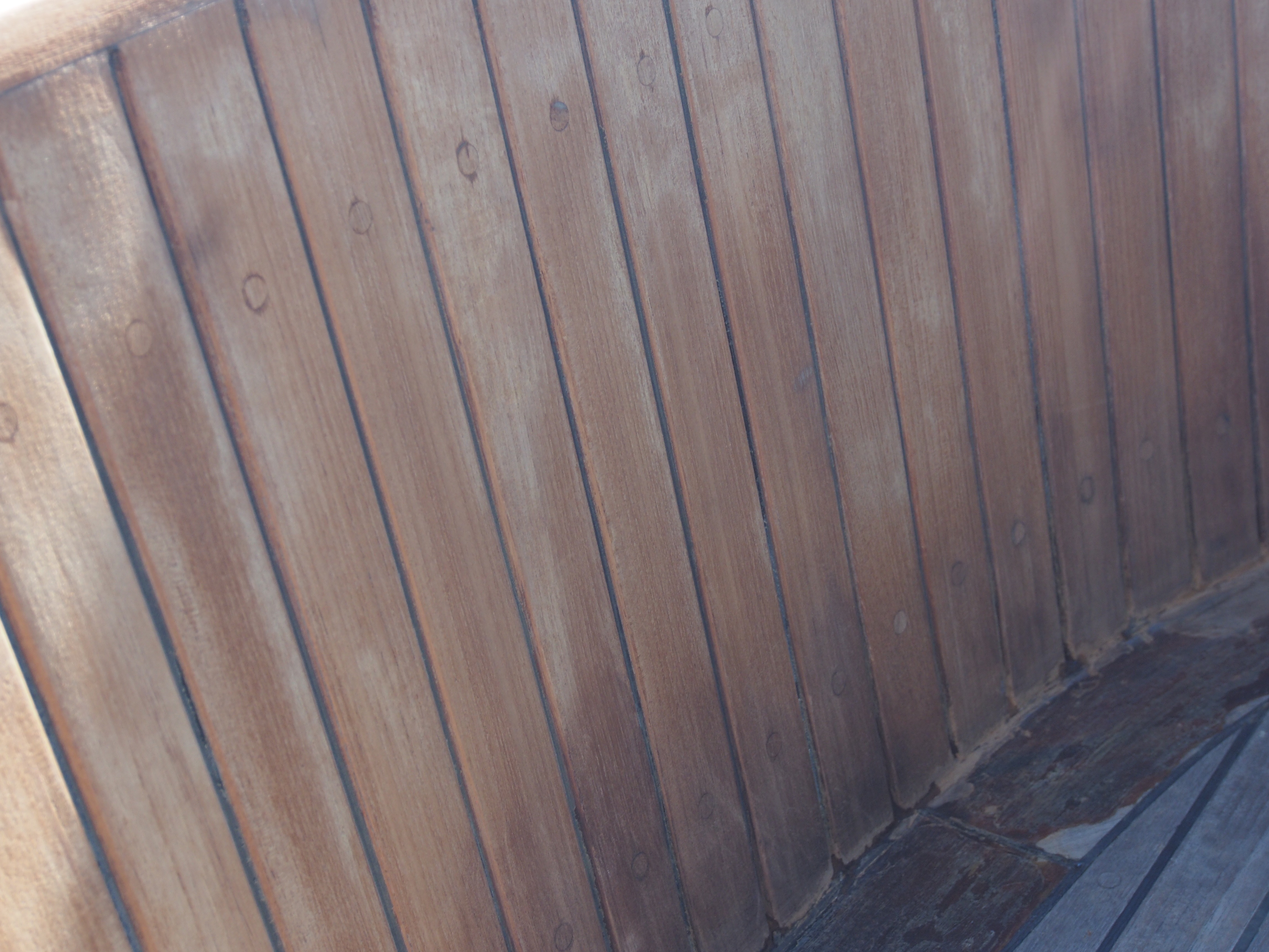
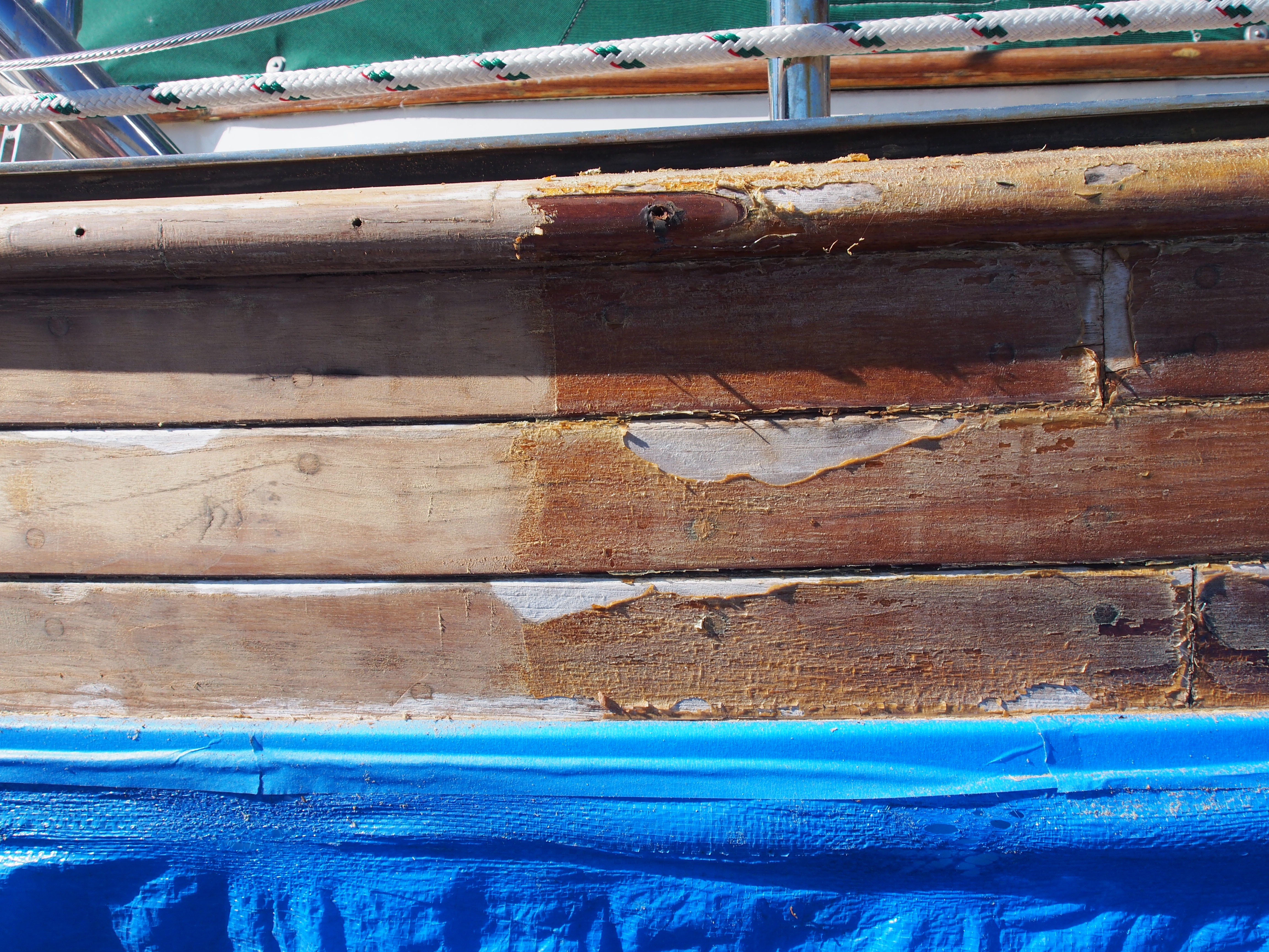
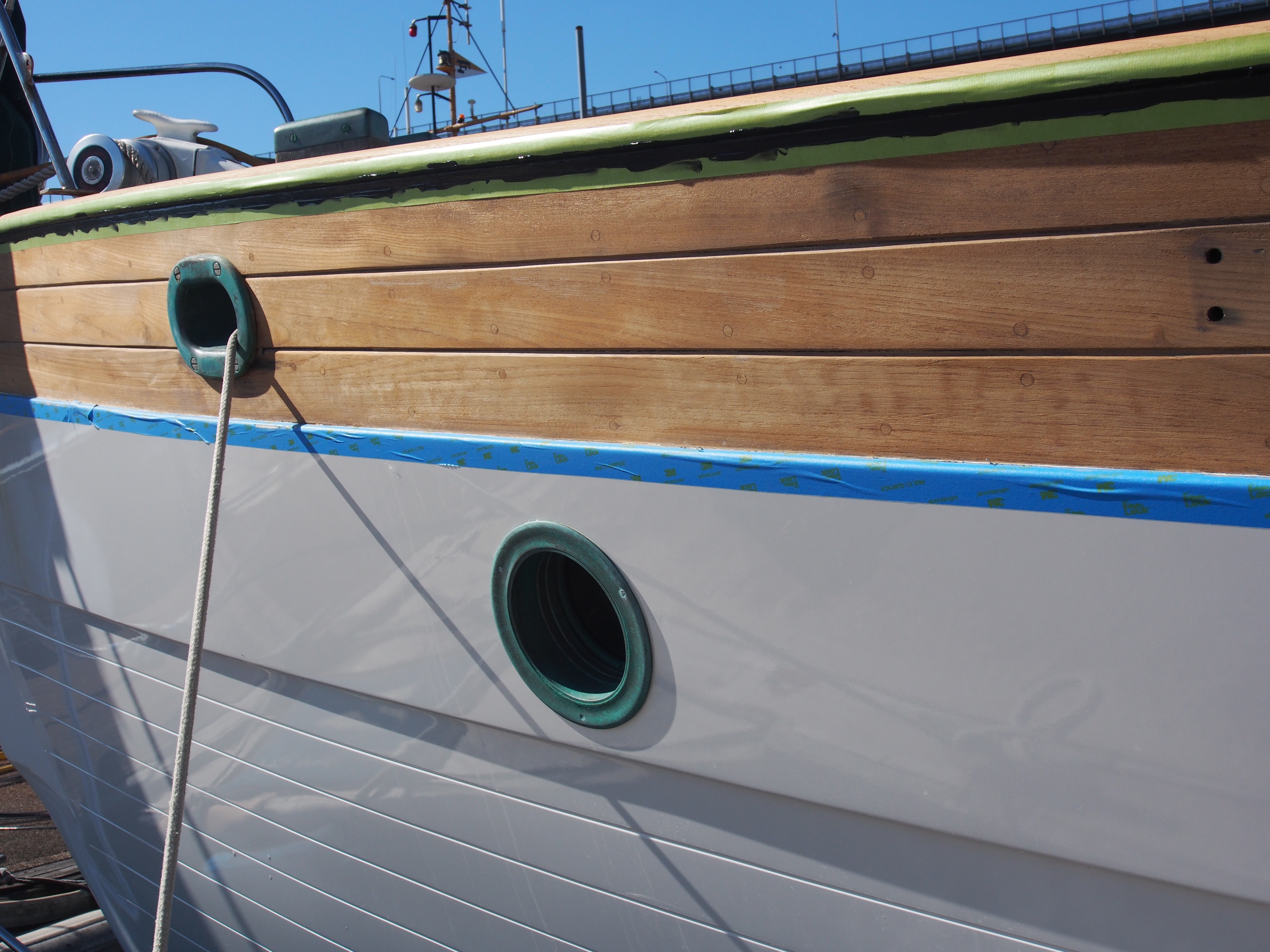
This is why I cover the boat during most of Seattle’s winter: