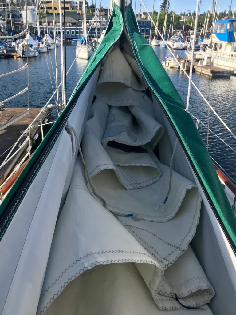
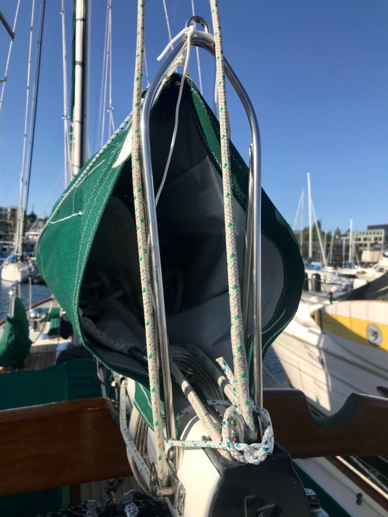
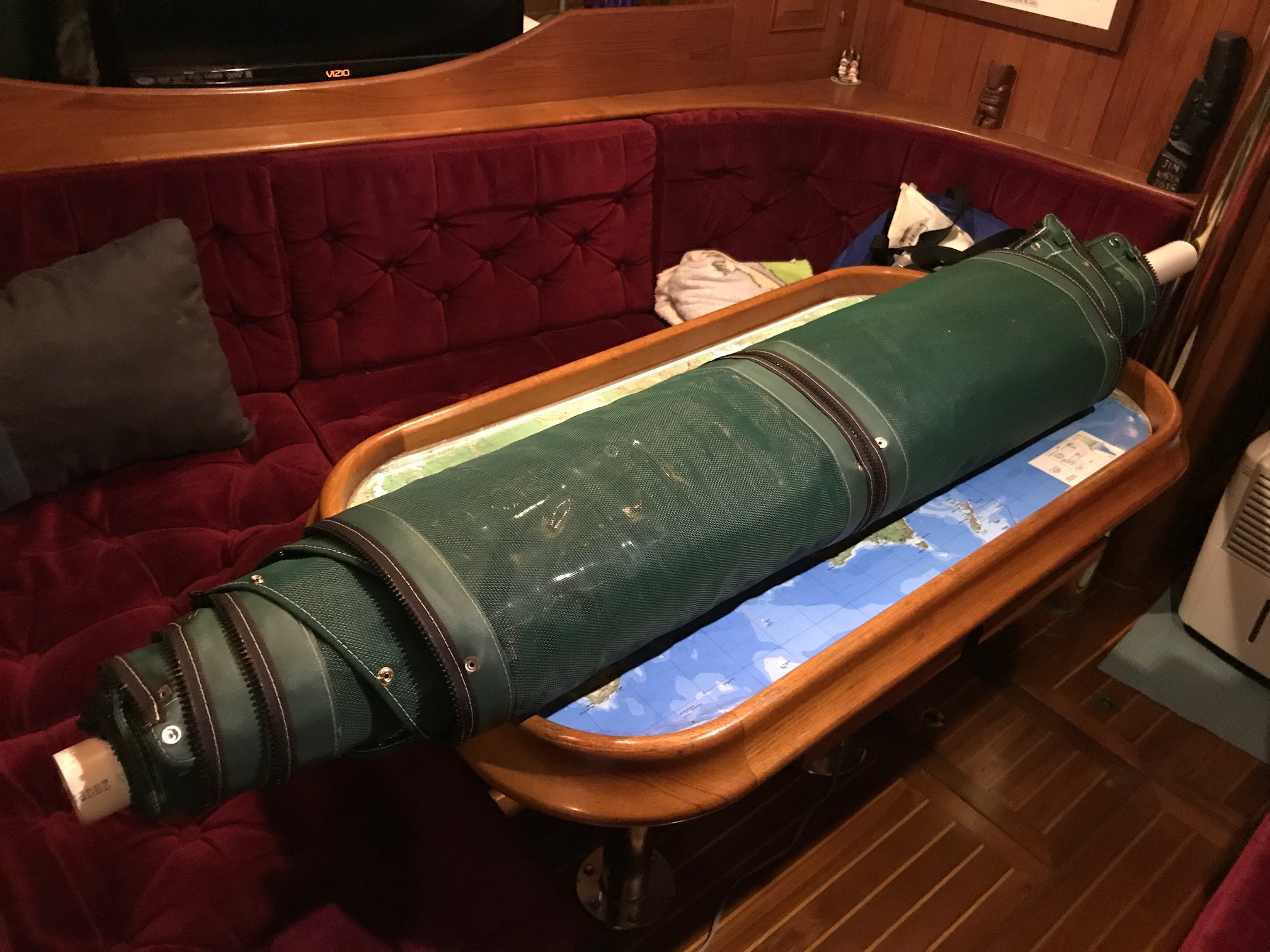
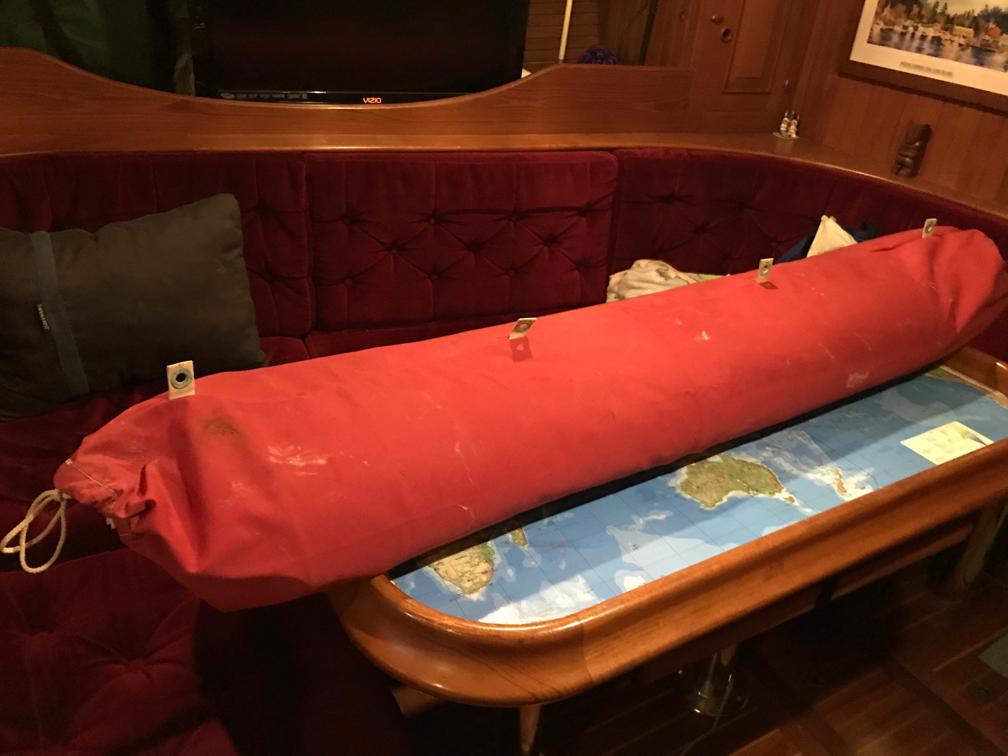
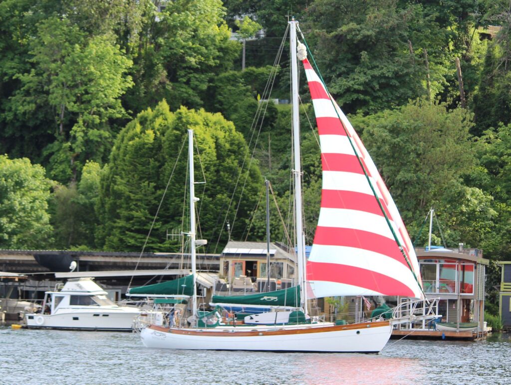
A drifter sail made from lightweight nylon came with Apropos. It’s a simple panel-cut sail that’s flown aft of the headstay and is pulled up in a sock. I just recently started using it more and am able to get it out while sailing single handed. It tacks easily if there’s some wind, otherwise it needs some help getting around the stays’l stay. With increased wind, it takes a lot of effort to dowse. And because it needs to be taken down after each sail, stuffed into a bag and stowed below decks, I was looking for something that was easier and didn’t have to be taken down after each sail or when switching to the Genoa if the wind suddenly picked up. I also wanted something more modern that had a better sail shape.
I began reading about Code Zero sails and learned that they originated from the racing scene to get around rules governing spinnakers. Eventually, furling Code Zeros were adopted by cruising boats, and are now becoming quite popular.
A cruising Code Zero looks like a genoa on steroids. Think of a 180% genoa and you start to get the picture. It’s intended for lower wind speeds (typically below 20 knots) and does best at wind angles between 75 and 125 deg. A Code Zero is flown out in front of the jib stay and is set up for roller furling, which is important for cruising boats and short handed crew. You just have to hoist the stay with the sail furled around it by using its halyard and then unfurl the sail from the cockpit. When tacking or gybing, just furl it in using the continuous line furler, change direction, then unfurl. When done sailing, or when the wind picks up and you want to switch to the Genoa, just furl it up and leave it in place since the sail has a UV protection strip.
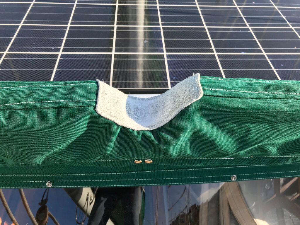
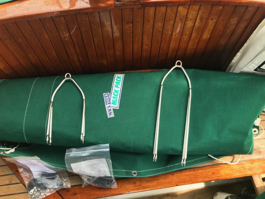
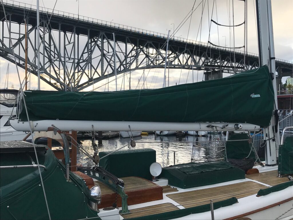
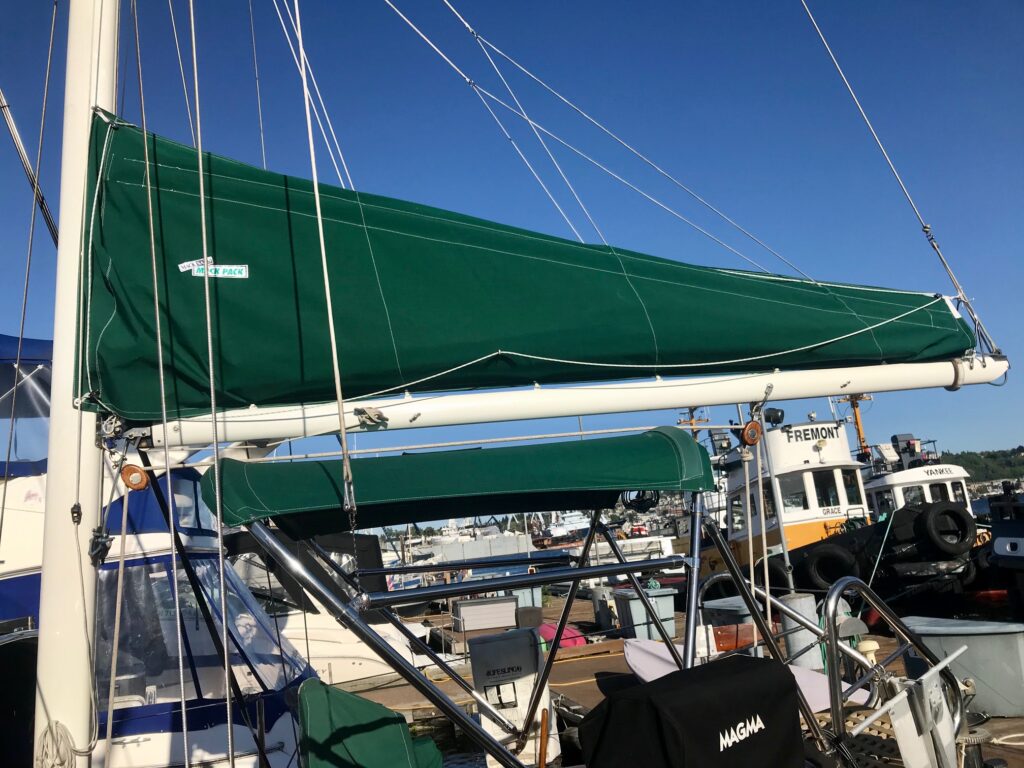
I decided to use Mack Sails for the complete Code Zero system–sail, furling hardware, and boat modifications. I was very please with co-owner Travis and his customer service, quality workmanship, and delivery time when I had them make my Stack Packs. For the Code Zero, I sent Travis 6 measurements and chose the color pattern. The sail fit perfectly.
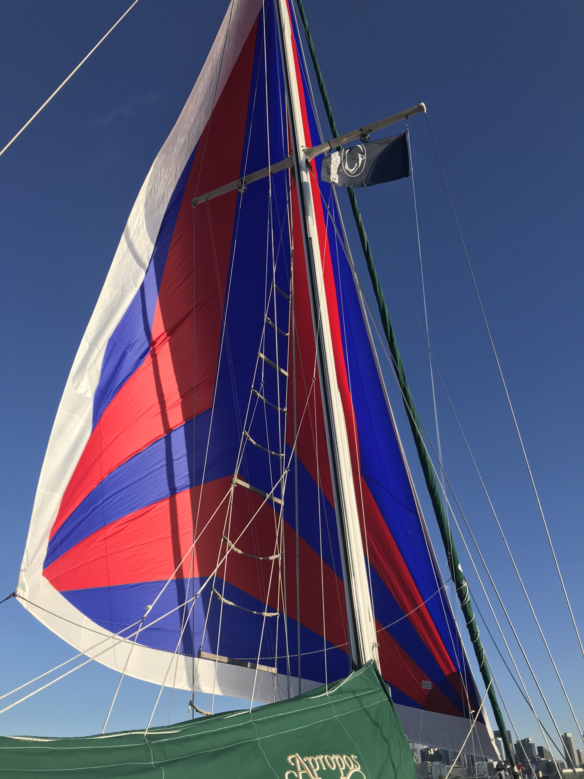
Tri-radial Sail
The sail material is 2.2oz nylon. The dimensions are Luff 49.67′, Foot 34.25′, Leech 46′ for a total area of 871 square feet (for comparison, my Genoa is 560 square feet). It’s tri-radial cut with 30 panels and dacron along the foot and leach to protect the nylon sail when it’s furled.
Furling Gear
The furling gear is a Bamar RLG 20 Evo. Bamar is a German company that casts their furler in bronze. My boat size was right near the cutoff for furler size, so we went with the bigger one (good for larger boats).
Boat Modifications
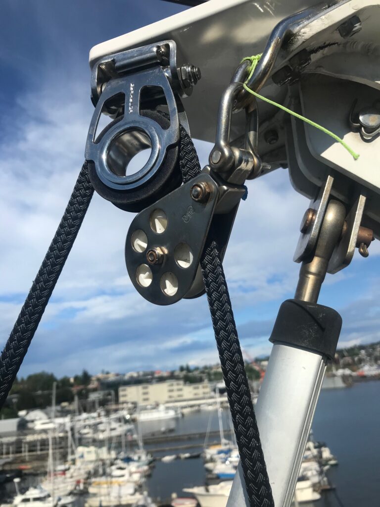
Since a Code Zero is flown out in front of the headstay, I had to add some hardware at the masthead and bowsprit.
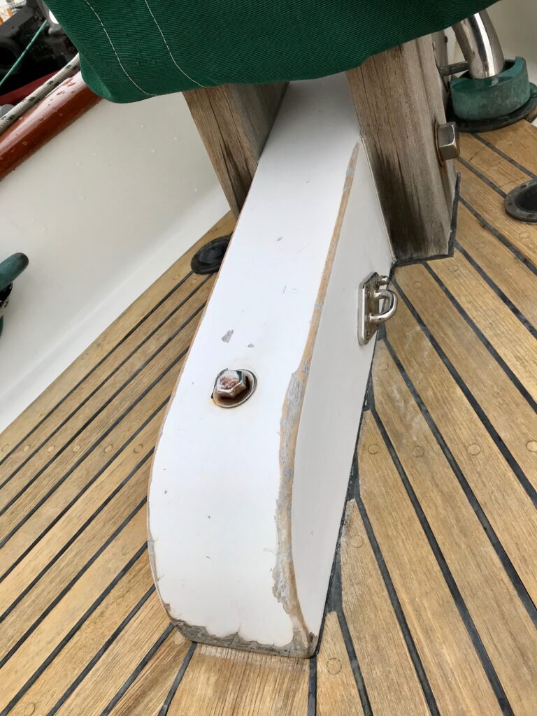
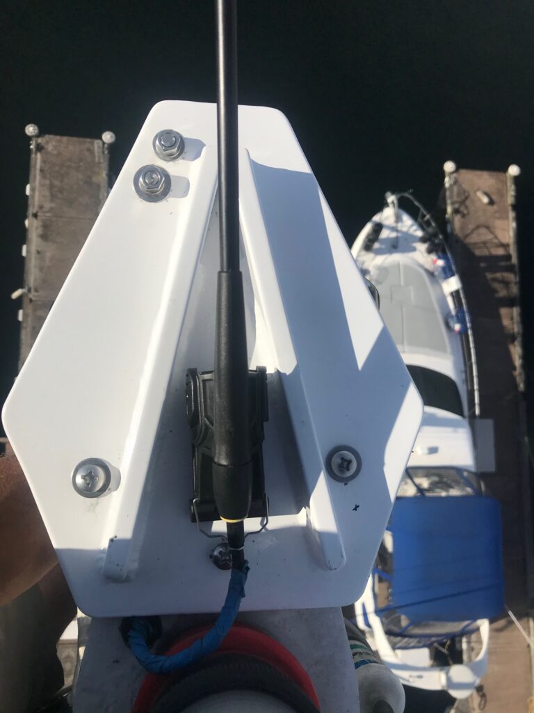
The masthead needed a bolt-on extension added to position the top furling gear away from the jib furling gear. I took measurements and made a drawing of the masthead, and a machine shop fabricated the 1/2″ thick aluminum extension with stiffeners. They painted it white to blend in with the masthead. A flip-flop block is mounted on the bottom. The halyard goes inside the mast, exiting a few feet from the masthead, goes through a block that’s mounted on the port-side stainless steel tang (used for spinnakers), then up through the flip flop block. I attached the extension using 4 5/16″ bolts–the 2 outer ones were thru-bolted and the 2 inner ones required tapping. Then I re-mounted the anemometer on top by tapping threads into the extension. The installation took 3 hours and I really appreciated the 2 mast steps I installed that puts me about waist high to the masthead.
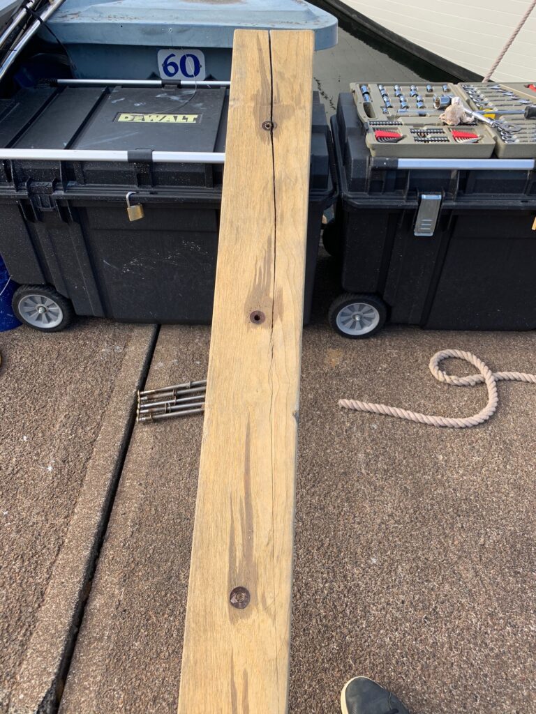
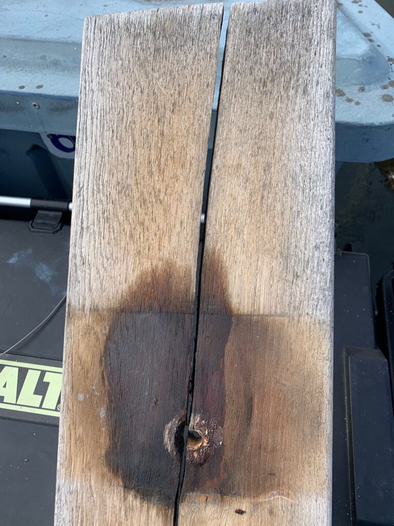
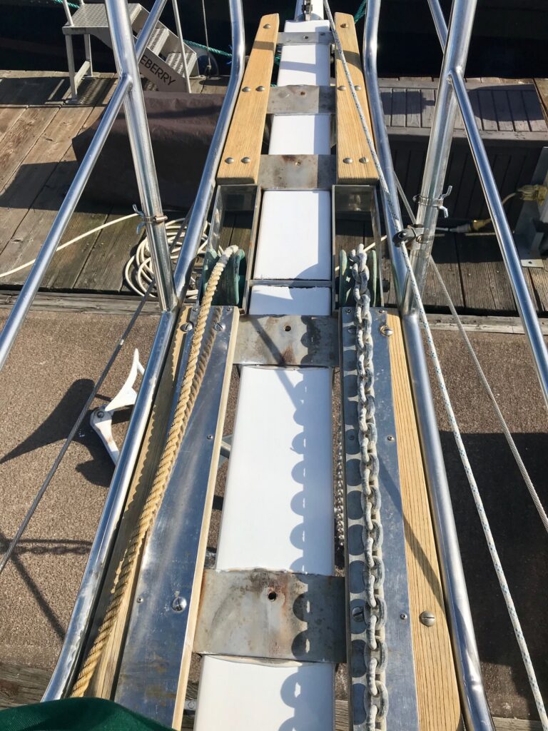
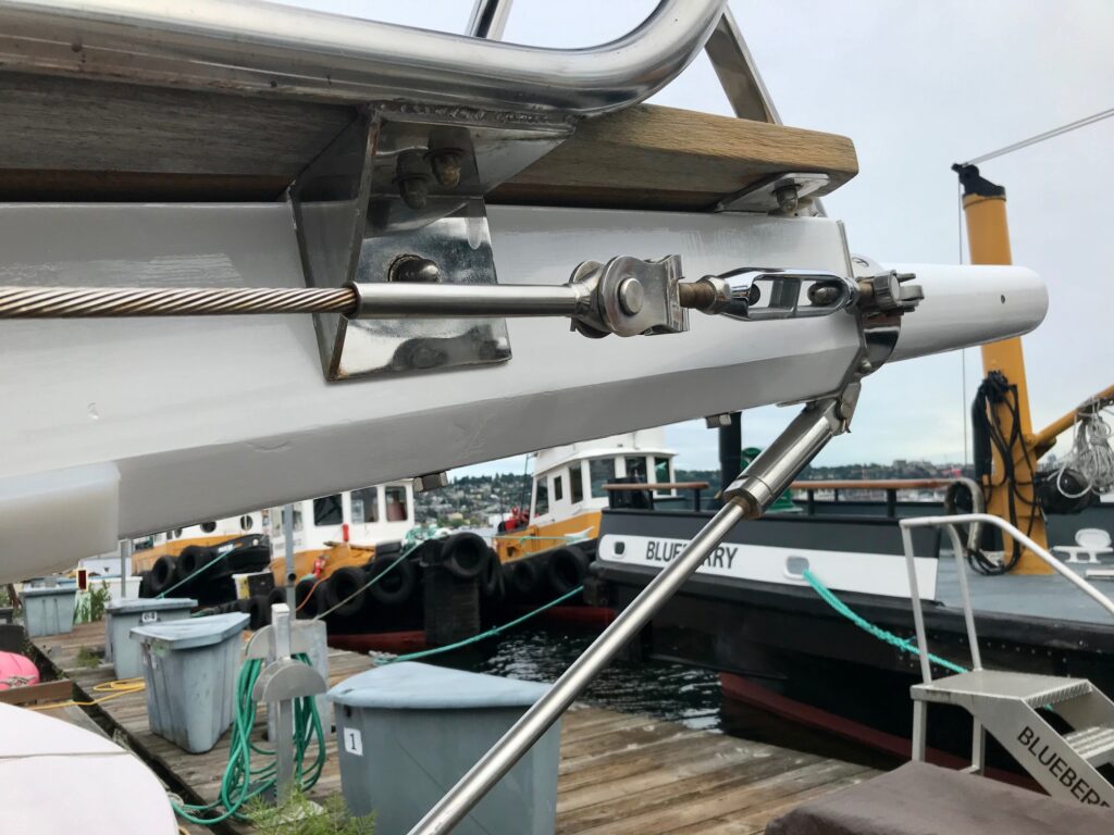
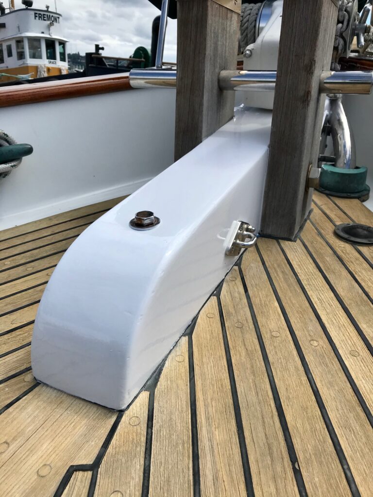
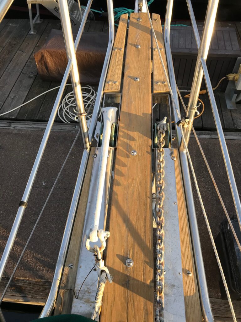
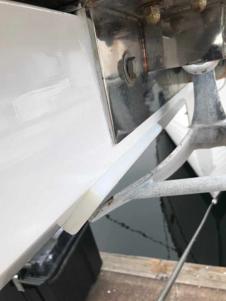
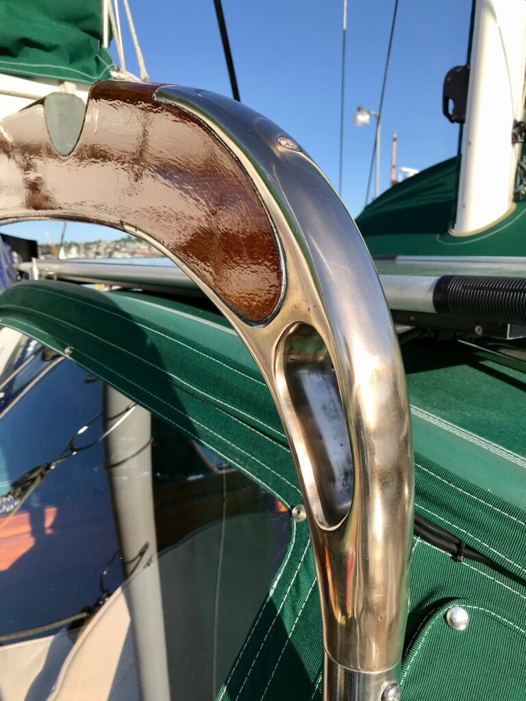
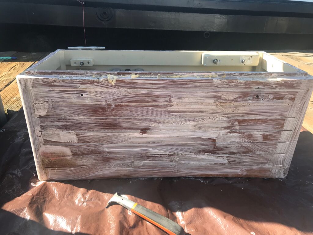
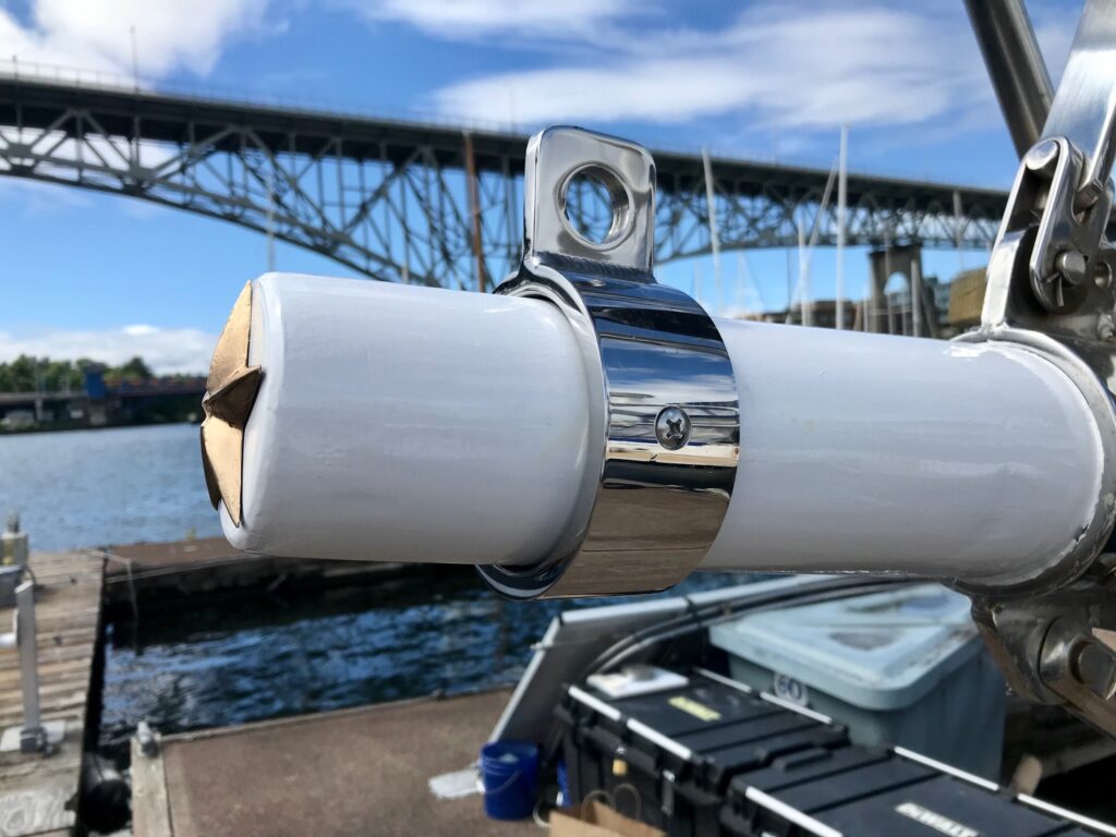
The bowsprit needed a collar similar to the cranse iron, but about 8″ closer to the tip. A machine shop found the right diameter stainless steel pipe and first sent me a 1″ piece to test fit since the bowsprit tip is tapered. It fit perfectly, so they cut a 2″ piece, polished it, and drilled & counter-sunk 2 holes for fastening it to the sprit. I drilled 2 oversized holes and filled them with epoxy, then screwed the 1/4″ x 1-1/4″ screws into the epoxy. An eye was welded to the top and is the attachment point for a cable that will hold the bottom furling gear.
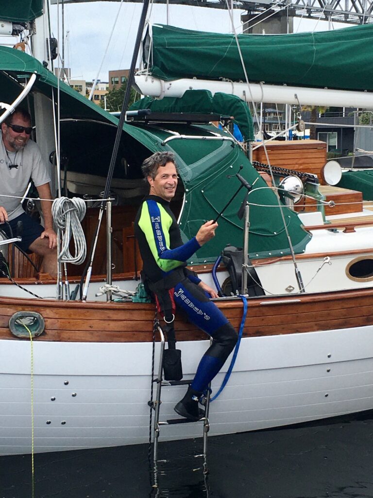
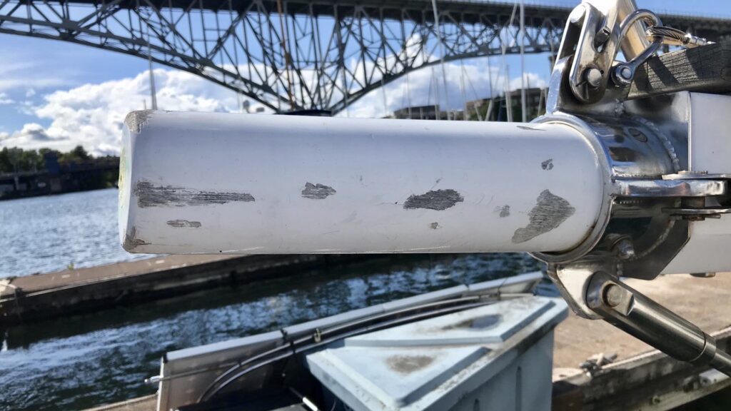
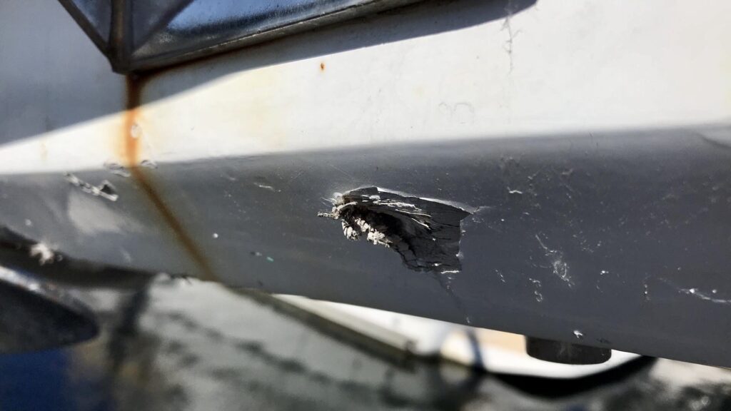
Side story–when I went aloft to test fit the masthead extension, I first removed the anemometer. Being extra careful not to drop the masthead extension (which weighs a couple of pounds and would do major damage to whatever it hit), I accidentally dropped the anemometer and watched it bounce off the side rail and fall into the water. Two days later I rented a tank and went scuba diving, recovering the anemometer in 45 feet of very murky water with a few feet of silt on the bottom!