This video was taken from a drone while sailing in light wind on Lake Union with a Drifter.
Wireless remote for windlass and bow thruster
Adding a wireless remote to the windlass has 2 benefits–it gives redundancy to the foot switches (we recently discovered the “down” switch worked intermittently due to corrosion on the terminals), and it also allows controlling the windlass from different locations on the boat (the foot switches are right next to the windlass). Adding wireless control to the bow thruster was an added bonus since the controller I ordered had 4 relay outputs for Up, Down (windlass) and Left, Right (bow thruster). I can see where the wireless bow thruster control will come in handy when the person controlling the windlass from the bow may need to align the boat to the anchor rode by using the thruster (the main bow thruster control is located at the helm).
I found a rugged (non-marine) wireless controller that was advertised as an industrial crane hoist controller. And it was only $55, compared to $300 or more for ones built specifically for a windlass, so I thought I’d give it a try. The model I bought was made by a Chinese company and came with a wireless remote that has 4 control buttons (Up, Down, Left, Right) and a Power On and Power Off. The instructions were all in Chinese but I was able to figure out the connections from the schematic printed on the controller box. The controller has 4 outputs, so I will also try to connect it to the bow thruster using the Left/Right controls. Aside from the wireless radio circuitry, the controller is basically a bunch of relays that perform the same function as the windlass foot switches–providing a 12V control signal when a button on the remote is pressed. My Lofrans windlass uses a controller made by Imtra. My bow thruster has a built-in controller. Both of these controllers use low-current 12V signals to activate relays that switch the high-currents to the windlass and thruster motors.
The installation was very easy since everything is located under the v-berth (windlass control, windlass and bow thruster batteries, bow thruster controller). This area is a dry locker and is separated by a bulkhead from the anchor locker as shown below. I powered the wireless controller with a switched 12V that turns on when the Windlass is activated at the DC panel. I used inline fuses for both the controller power and the controller output source power.
Wireless Controller (says 24V but also works with 12V)
Wiring completed to Bow Thruster (bottom) and Windlass Control (top)
Remote controller for wireless Windlass/Thruster
Total time to install and test was about 6 hours, total cost was $55 for the wireless system and $20 for wire, terminal connectors, and fuse holders.
Wind Sensor Project Update
Note: This post is probably not interesting or relevant to most readers–it’s a detailed account of a specific project that I put a lot of time and effort in. Some boat owners may find it useful if they have a similar problem.
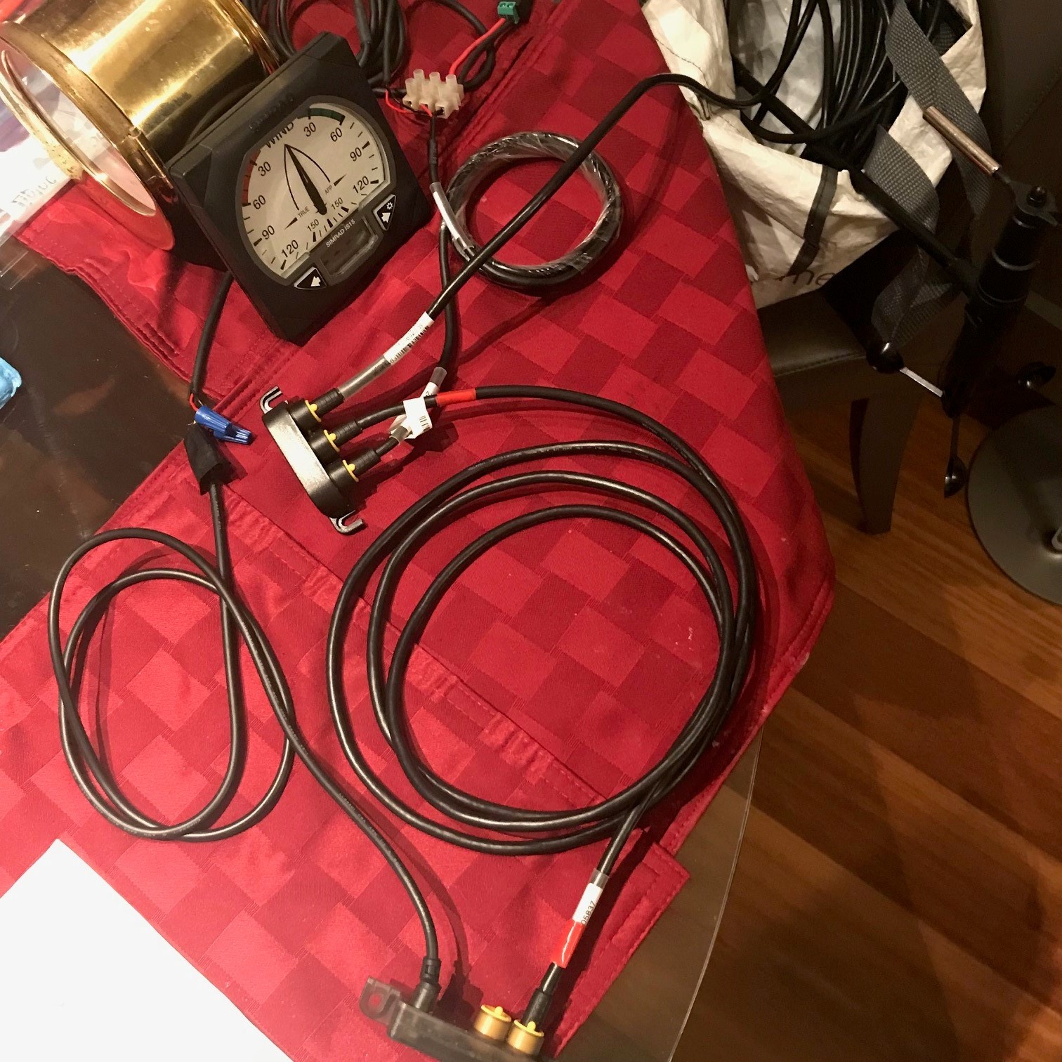
The project began over 2 years ago when I returned to my boat in Fiji and discovered the masthead wind sensor was gone, thanks to Cyclone Winston. The sensor was part of the Simrad IS-15 wind/speed/depth/rudder position system that uses the NMEA 0183 protocol. Unfortunately, B&G (formerly Simrad) didn’t have replacement IS-15 wind sensors, so I bought the newer IS-20 sensor along with the necessary parts needed to convert an NMEA 2000 signal to an NMEA 0183 signal needed by the wind display instrument. Many hours were spent trying to get the new wind sensor to move the indicator on the display, but to no avail. We ended up sailing over 6000 nautical miles from Fiji to Seattle without any wind speed/direction.
Back in Seattle, I re-started the effort to get the wind sensor working. I brought the system home and set it up on the kitchen table to debug the problem. I used the diagram from B&G tech support shown below. It’s not very complicated, but it still didn’t work.
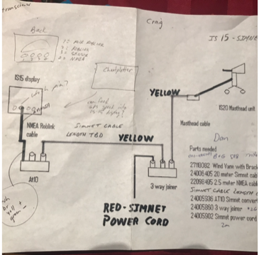
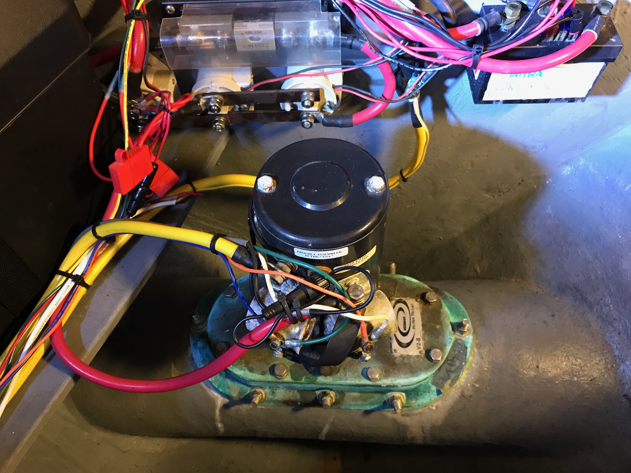
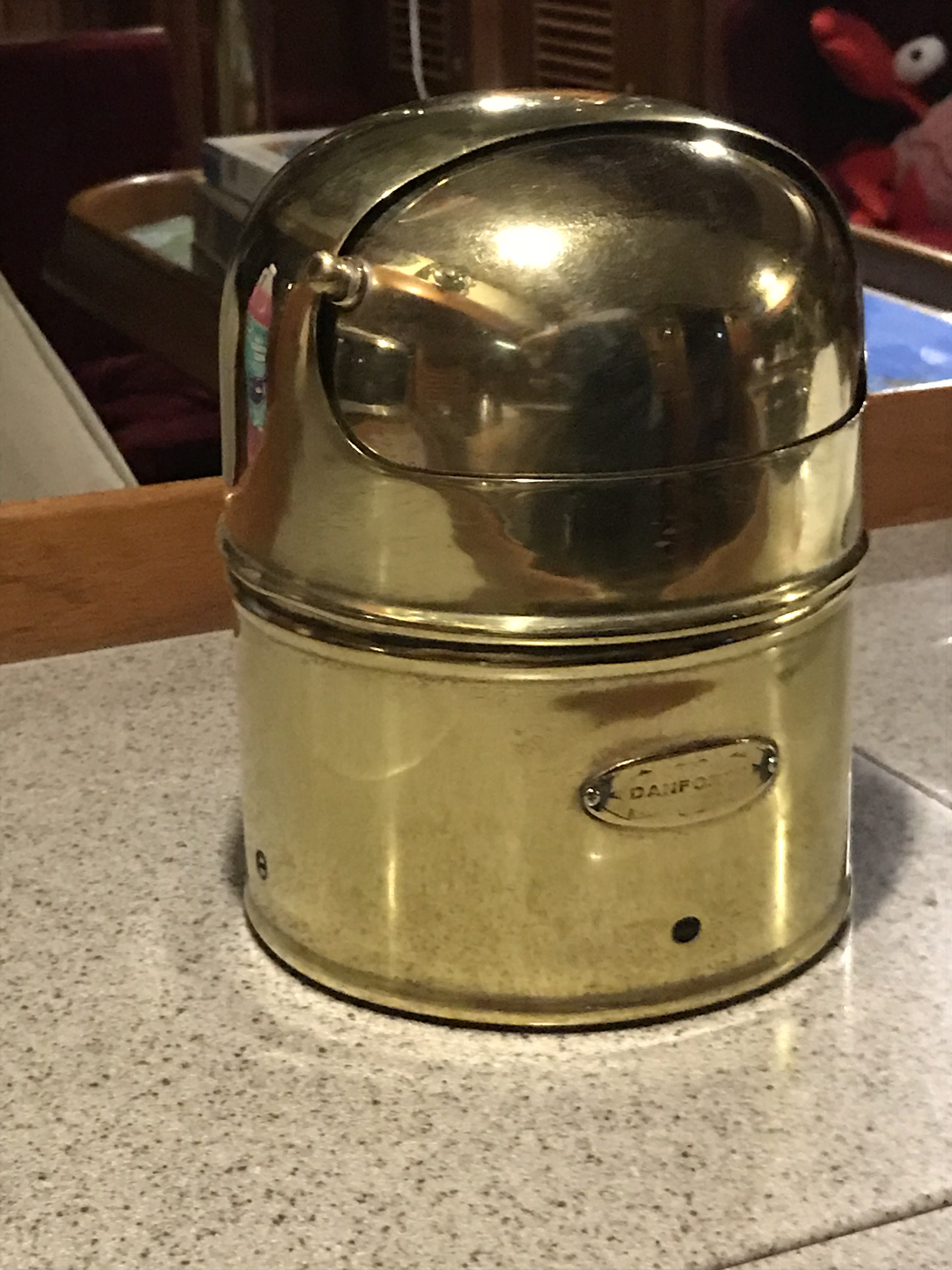
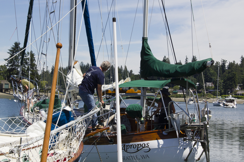
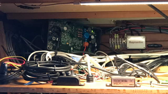
There are 2 parts used to convert the signal from NMEA 2000 to NMEA 0183–a 3-way joiner and an AT10. Since the system still didn’t work, I suspected I had a bad part so I bought a new AT10 and then it worked! After I had the system shown in the diagram working, I took it back to the boat to install. But there was 1 more piece to the system, a Simrad transceiver with inputs for wind, speed, and depth that multiplexes to a single output that goes to the wind, speed, and depth display instruments. Since the transceiver is installed at the navigation station (behind the main panel), I installed the 3-way connector and AT10 next to it (shown in the picture below with the transceiver box cover off).
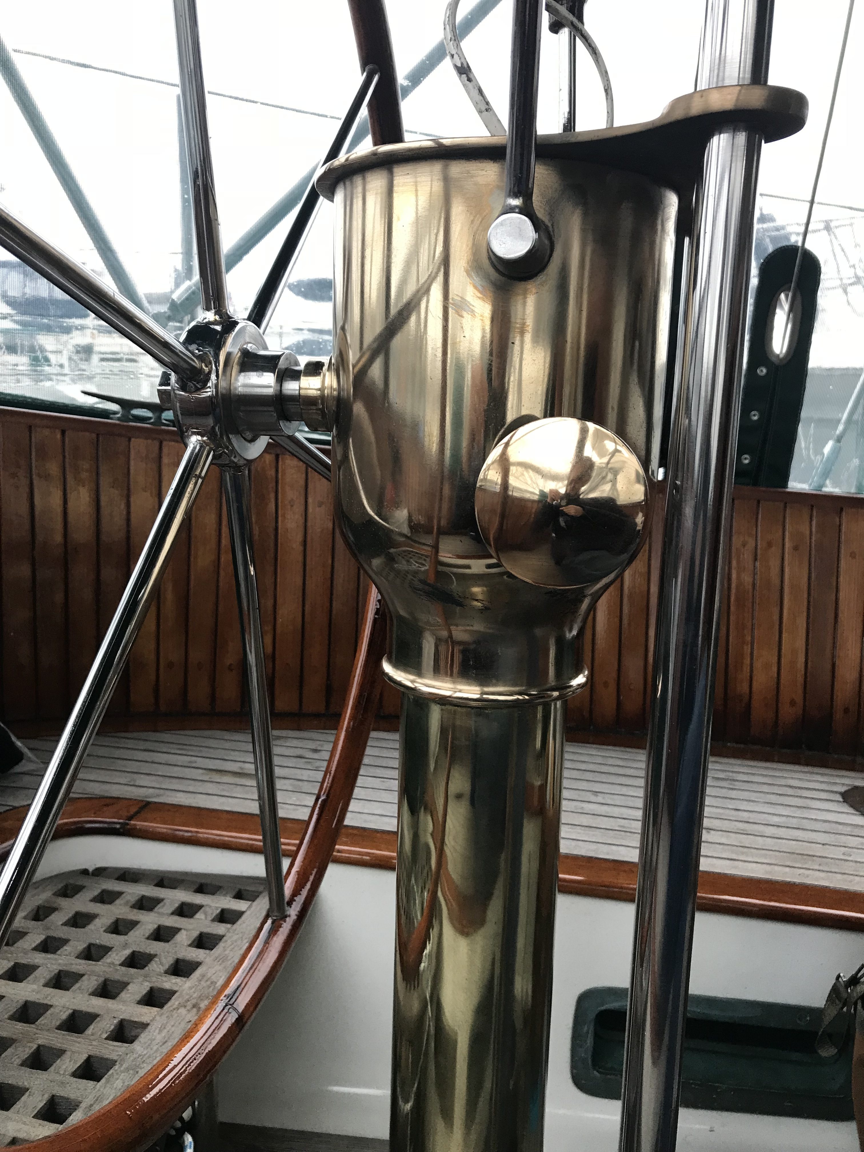
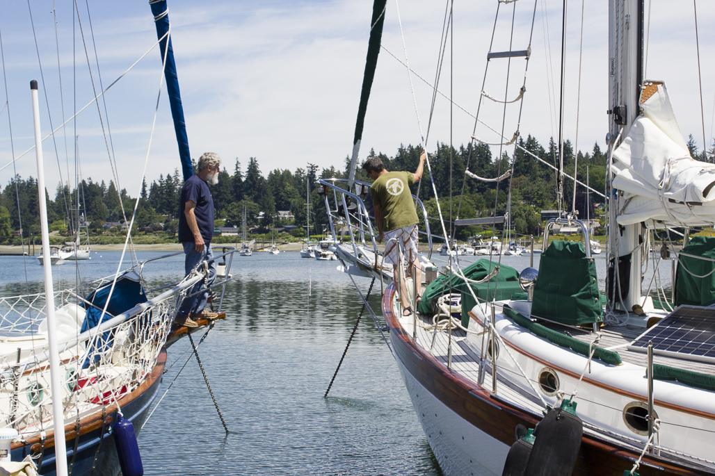
Next was to run the wire from the 3-way joiner to the mast head where the wind sensor will be installed. Unfortunately, the existing wire and connectors were not compatible with the new wind sensor. The first step was to run the wire to the base of the compression post, about 15 feet away. This section went through cabinets and the settee before reaching the bilge near the base of the compression post. I cut the wire there and installed a junction box for easy disconnect when pulling the mast.
The final step was to pull the new wire through the compression post and up the mast. This turned out to be impossible because the existing wire would not budge either way. There are a total of 6 wires going through the compression post and mast for 2 spreader lights, a vhf antenna, masthead running, strobe, & anchor lights, a steaming light, and the wind sensor. Inside the mast, they are run in a conduit along the aft side of the mast. I suspected the wires could be taped together inside the mast as they exit the compression post and make 90 degree bends before they enter the conduit as the reasons for not being able to pull the existing wire. I considered pulling the deck-stepped mast to do the wiring, but the cost was going to be close to $1000 (crane fees, rigger fees) plus a whole lot of work (removing sails and boom, disconnecting all the wiring, loosening all the stays, getting the boat to yard). Since the cost and amount of work didn’t seem worthwhile for running a single wire, I thought of an alternative.
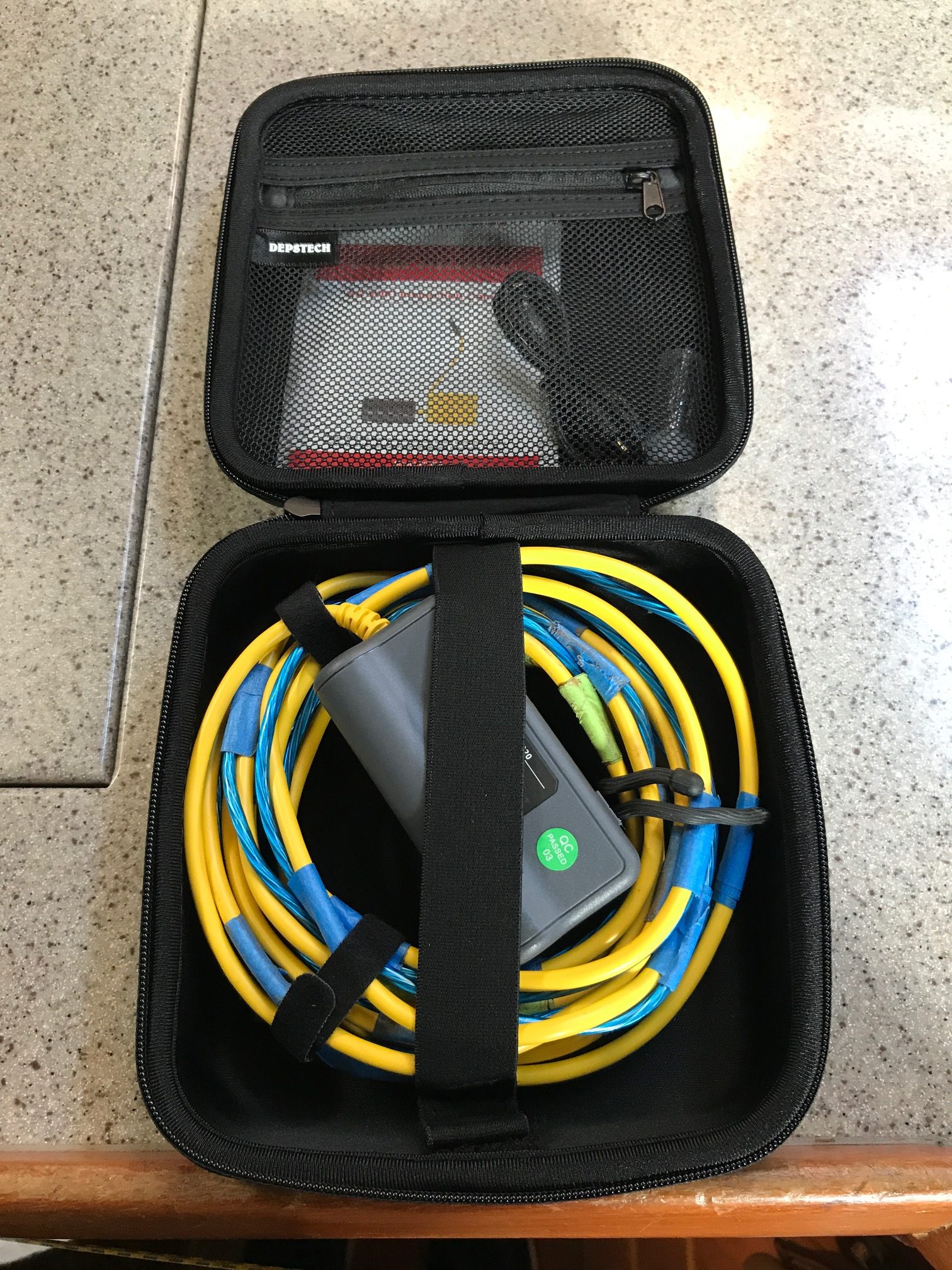
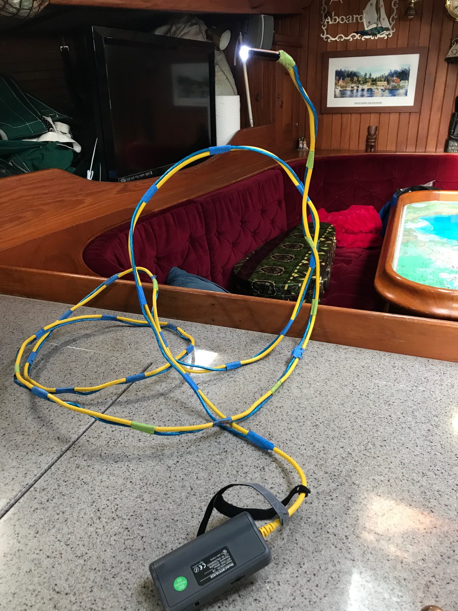
I purchased an endoscope for $40 on Amazon (Depstech Semi-Rigid Wireless Borescope WiFi Inspection Camera 2.0 Megapixels HD 1800mAh Lithium Battery Snake Camera – Yellow 11.5FT ). It uses a Wifi connection to display the camera images on smartphones. 
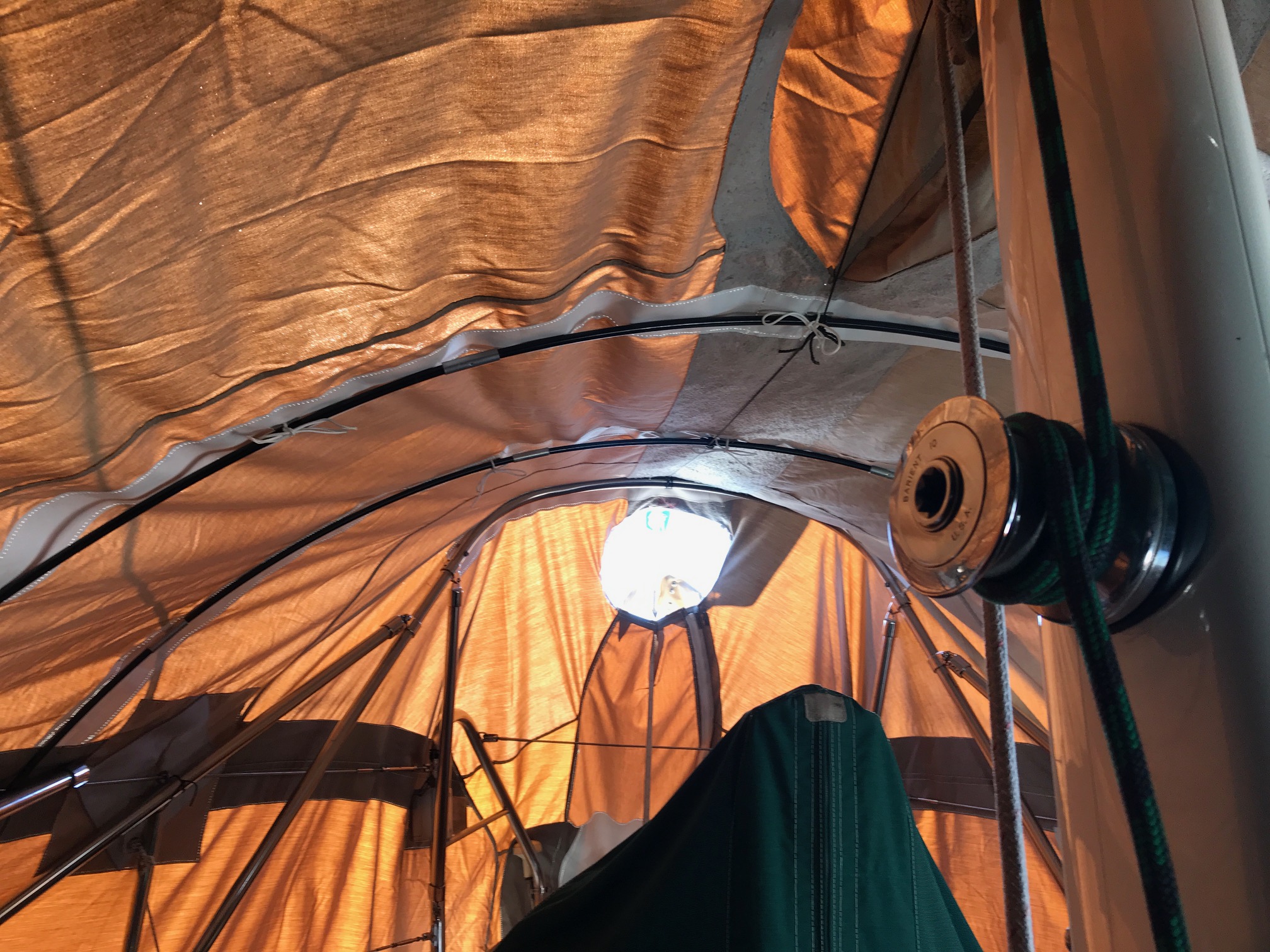
My plan was to feed the endoscope down a halyard exit hole on the side of the mast about 6′ above deck level to see what the wiring looked like near the mast base. The first thing I noticed was the 11′ semi-rigid wire was too flimsy, especially when feeding it long distances. So I taped an 11′ plastic-coated wire along side it to give it more rigidity. It took some practice but I was able to manipulate it to see the wiring near the bottom of the mast where it exits the conduit. The focal point of the camera lense is about 6″ and the intensity of the blue LEDs can be adjusted. I took video and pictures, below are some of the pics.
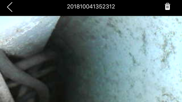
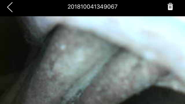
The top pic shows most of the wires as they exit the compression post. The smaller diameter grey wire is the wind sensor wire. The bottom pic shows the wires exiting the mast conduit and the smaller grey wire can be seen between the 2 larger diameter spreader light wires.
Next I decided instead of pulling the mast, I would cut a 7/8″ diameter hole about 3″ from the base of the mast to try to get a better view of the wiring. My mast is 3/8″ aluminum, plenty thick enough for a small access hole to have no affect. This allowed me to get a better shot of the wiring with the boroscope, and sure enough the wires were taped together in a bundle right as they exit the compression post.
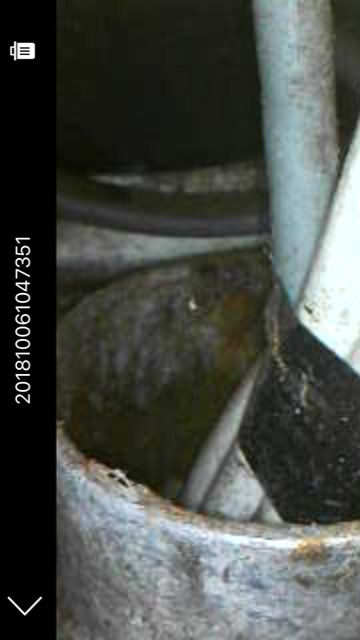
The 7/8″ hole allowed me to use a long screwdriver to break the electrical tape then grab the grey wind sensor wire with needle-nose pliers and pull it out the access hole. Next I taped a feeder string to the end of the grey wire at the bottom of the compression post (in the bilge), and pulled it up through the compression post and out the hole. Then I taped the new wind sensor line to the feeder string to pull the new line. I had to tug on the feeder line quite hard to squeeze the larger diameter connector on the end of the wire through, so I also used some thin black tarred seine twine to tightly wind over the tape to make sure it didn’t slip as I pulled. I also used liquid soap along the length of wire to make it more slippery. It all worked as planned and I pulled about 75′ of wire from the bilge to the access hole at the base of the mast.
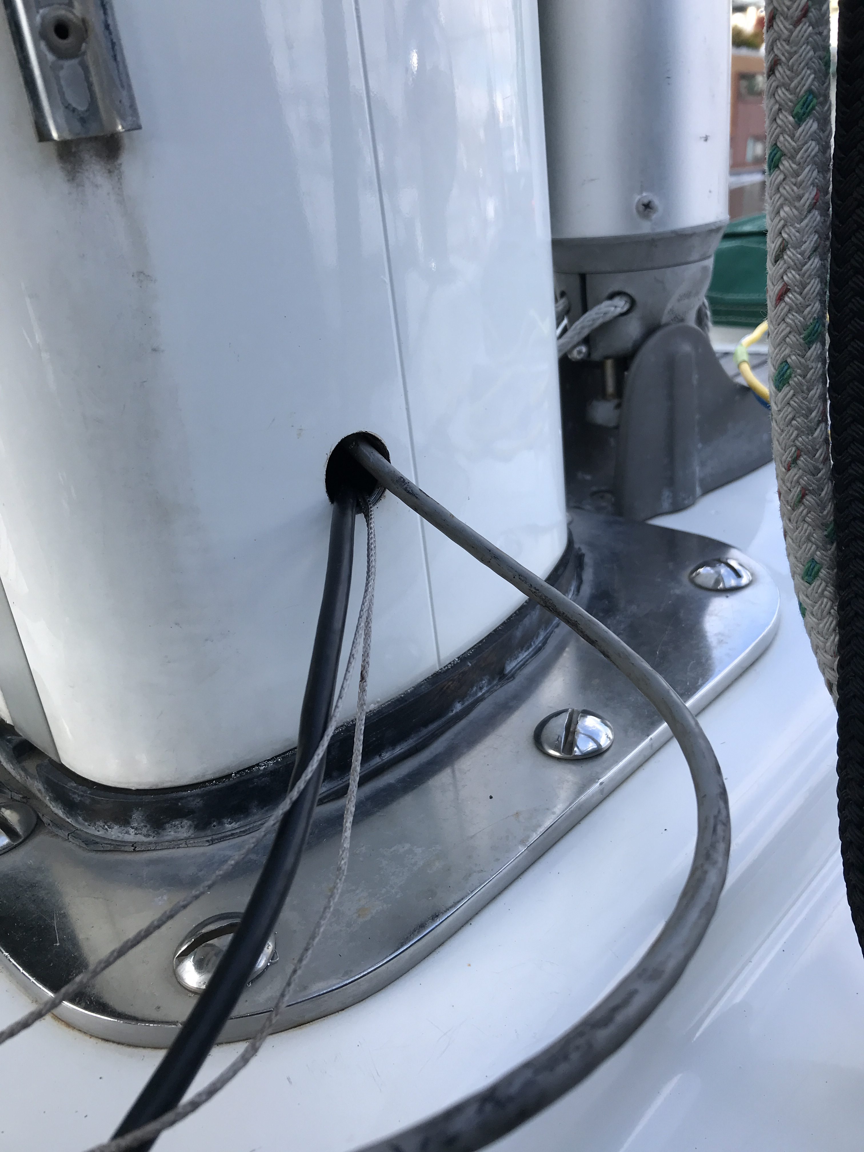
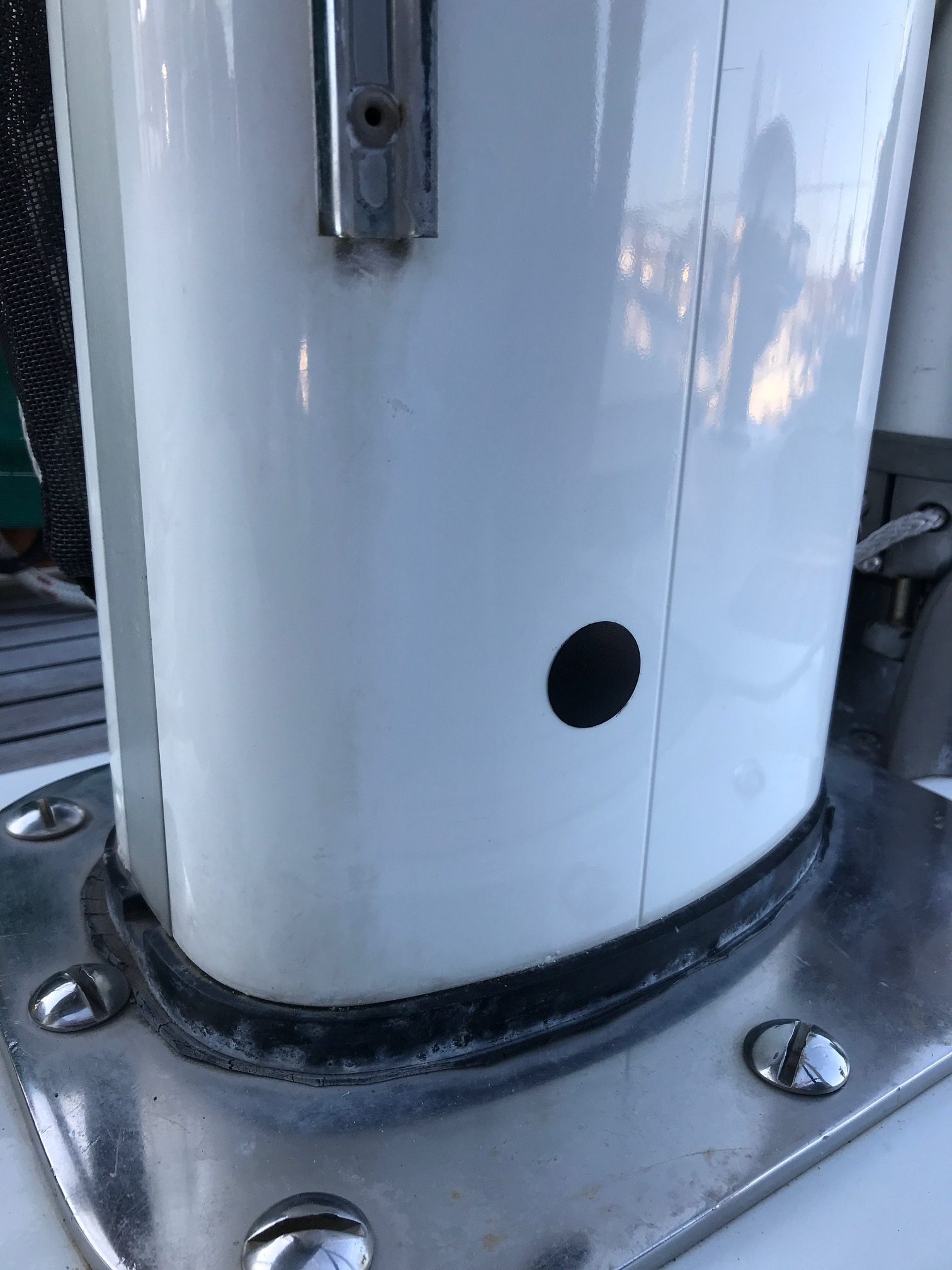
Here’s a picture of the access hole on the starboard side of the mast with the new NMEA 2000 wire (black) coming out. The old NMEA 0183 wire (grey) goes to the mast head and will be used to pull the new wire 58′ up the mast. The dynema string is a tracer pull-line through the compression post that will be left in case it’s needed in the future. After the wire was pulled up the mast, I capped the access hole with a plastic cap.
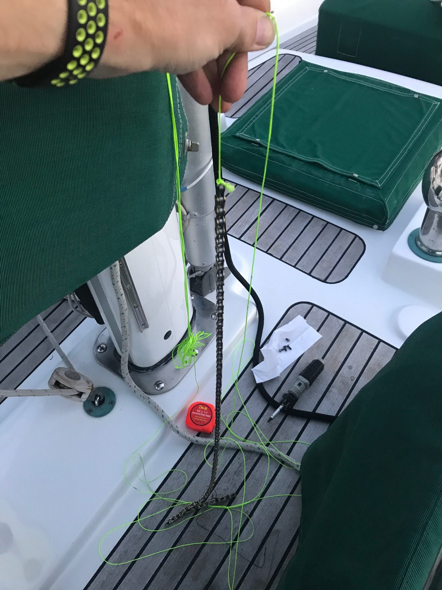
The final step was to run the wire up the mast. I thought it would be easy. I was wrong. Since I could not pull the old wire up though the conduit, I decided to run the new wire inside the mast (but not in the conduit). So I bought a bicycle chain to tie onto the end of a string and lowered it from the top of the mast. The weight and flexibility of the 3′ bike chain allowed the feeder string to go all the way down the mast to the base, where I was able to fish it out the access hole. So far, so good. Next I fastened 3 long zip ties around the wire about every 10 feet. By not cutting the ends off the zip ties and offsetting them by 120 degrees, this trick should buffer the wire from hitting the sides of the mast as the boat rolls and pitches. Next I securely taped the new wire to the bike chain, then went up the mast again to pull it up. About half way up the mast, it got stuck! Since I couldn’t pull it up (I tugged as hard as I dared) , I tried lowering it but it wouldn’t go down by gravity. I went back down to deck level and tried to pull it down, but it was stuck. I finally pulled hard enough to free the wire from the chain. Since my string was 100′ long, I decided to feed down more string from the top of the mast. Gravity took it all the way down to the bottom, where I was able to fish it out the access hole. Next I tied the new wind sensor wire to the string, returned to the top of the mast, and successfully pulled it all the way up the mast. I mounted the new wind sensor at the masthead on a quick release bracket and plugged the wire into the sensor, flipped on the navigation equipment, and the wind instrument came to life, showing speed and direction! Success. Sort of. The bloody chain was still stuck somehow/somewhere inside the mast, with a string attached to it the came out the top of the mast. I tested all the halyards that run internal to the mast and they all move fine. My only thought is that there must be some pinch point near the spreaders that has wedged the chain. For now, I’m leaving it. I’m taking the boat out sailing tomorrow and will enjoy the wind instrument and try not to think about the chain that is stuck somewhere inside the mast! Another project for another day….
UPDATE: When I pulled up the drifter halyard today, the chain that was stuck inside the mast came tumbling down to the base of the mast and I was able to fish it out the small access hole. Problem solved!
Hans Christian Puget Sound Rendezvous
We sailed across Puget Sound to Poulsbo for a fantastic weekend gathering of Hans Christian sailboats. Five boats showed up–3 HC43s and 2 HC38s. One of the 43’s was a sister-ship to my 43′ Ketch. We enjoyed meeting the other owners, touring their boats, and having a Mexican themed potluck on Cinco de Mayo. We also gathered for a Sunday morning breakfast before departing around 2pm. We hit our old favorites while in Poulsbo–Mora’s Ice Cream, Sluys Bakery, and Longship Marine Chandlery. Sailing was good on the way over, but we had to motor on the return trip.


Winter/Spring 2017-18 Boat Projects
I completed a lot of boat projects during the winter and spring. Some were left over from things that broke during our trip to the South Pacific, and some were completely new. Some projects took a day to complete and others took weeks. Here is a partial list:
- Chelsea Shipstrike Clock–the 10 year old mechanical clock worked intermittently by the end of our trip. When it stopped ticking, sometimes removing it from the bulkhead and shaking it would restart it. But eventually it stopped altogether. I got quotes from a local repair shop of $400 which included taking it apart to clean and lubricate. That seemed like way too much for a clock that sells for around $800. So, a bit of YouTube research, a $10 bottle of clock oil, and a few hours of my time was all that was needed to get the clock ticking again.
- Bilge Pump–the secondary bilge pump that turns on first to remove water from the bilge was an old diaphragm pump with a 12VDC motor with brushes! Probably original equipment so it must have been over 30 years old. During our trip I replaced the belt and internal diaphragms with a rebuild kit I brought along. The pump got a real good workout on the wet passage from Hawaii to Seattle with lots of water on the deck finding its way to the bilge. It also had an inline filter that I had to clean often because it was getting clogged up with dead cockroaches! Anyhow, I decided to replace it with a new pump that is half its size and pumps twice the GPH. The Whale Supersub Smart pump has automatic water sensing that uses no moving parts, and was easy to install. Since this pump sits in the bilge (the old one was located outside the bilge and had a hose going to the bilge), it required running new wiring and a new hose to a thru-hull. Total cost was about $125.
The old bilge pump
- Heat Exchanger–a marine diesel engine removes heat from the engine by passing sea water through a heat exchanger. The sea water passes through 54 copper tubes that are surrounded by fresh water (radiator fluid plus water) that circulates through the engine for cooling. Since saltwater runs through these tubes, they often get clogged and need to be removed for cleaning. The heat exchanger on my Yanmar engine sits on the side of the engine with not access, so removing it is challenging. The alternator needs to be swiveled away and some hoses need to be removed to gain access to the 2 end-caps. Once I removed the end-caps, I could shine a light through the tubes and found them to be surprisingly clean, with no buildup. This was probably due to the fact that since 2004 when the new engine was installed, the boat has lived in fresh water most of the time. Unfortunately I could not manage to slide the heat exchanger tube housing out of the heat exchanger, even tapping one end with a heavy mallet. I tried applying heat using a heat gun but there’s a lot of metal and it didn’t seem to get very warm. Since it looked very clean anyway, I decided to let well enough alone and not remove it. Using new O-rings, I reassembled the end-caps, turned the sea water valve back on, and water leaked from both end-caps. On my next attempt, I was more careful when seating the O-rings, and then I only had one end-cap leaking. But this was a different problem. I noticed the heat exchanger housing had corroded at the bottom lip of the end-cap. So as I tightened the end-cap bolts, the O-ring had nothing to push against so it wasn’t making a water-tight seal. I suspect there was a small leak that over time caused the metal housing to corrode. A new housing is around $2000, so I took a few days to think about how to fix it without buying a whole new heat exchanger. The O-ring is about 4″ in diameter, and the metal was corroded in only about 1/2″ of the outside groove. So I clipped a 1/2″ section out of the O-ring and seated the remaining O-ring (maybe now it’s a C-ring) in the end-cap groove. Then I applied high temperature gasket material where the 1/2″ gap was, hand tightened the end-cap bolts, let it sit for 1 hour, then fully tightened the bolts. After sitting for 24 hours, I opened the sea water valve and there was no leaks. I ran the engine for 30 minutes and still no leaks. I’ll keep an eye on it the next couple of times we take the boat out, but I think it’s a good fix.
End-cap removed from heat exchanger
RTV Gasket Maker applied to end-cap

After cleaning and applying gasket maker (this was before I cut the O-ring)
- Isolation Transformer–The marina recently upgraded its wiring to newer standards and throughout the winter, boats were tripping the more sensitive GFCI electronics. Eventually, the marina is requiring all boats to install isolation transformers. More common on boats in Europe, this is a safety device that helps prevent stray currents going into the marina water on boats that are not wired correctly or have a fault. Stray currents entering the water can cause muscles to cramp and result in electrocution and drowning of swimmers next to the boat. An isolation transformer magnetically isolates the shore AC power from the boat AC power. So it also protects a boat from faulty marina wiring. I decided to buy a Charles Industry “international” 3.5KVA transformer. The international part means that it can be configured to accept either 120VAC or 240VAC shore power, and output either 120/240VAC. So I could (theoretically) take the boat to Australia and, after moving a few jumpers to reconfigure the isolation transformer, plug into a 240VAC dock power and have 120VAC onboard. The transformer weighs a whopping 70 lbs with its iron core and windings. I used the space from where I removed the old bilge pump to install it–it’s a dry place and sits directly below the AC electrical panel. Since it didn’t quite fit, I had to saw a small piece off the bottom mounting bracket, then drill 4 holes and screw it down. Next I made the 4 required jumpers to configure it for 120VAC input and 120VAC output using 12 gauge wire. Next I ran new 3-strand 8 gauge wire from the shore input connector to the isolation transformer. The run was only 10 feet long but it took about half a day! There a 4′ section that you can’t see or feel, but the wire would not push through. 3-strand 8 gauge wire is pretty thick, so I ended up removing the sheathing and feeding each wire (hot, neutral, ground) through separately. I suppose I could have used the existing wire, but it wasn’t long enough to reach the transformer and I didn’t want any connectors. Plus I wanted all new wiring for such an important piece of equipment. Next I had to figure out how to wire the output of the transformer. I made a complete diagram of the boat’s AC electrical system, then researched (Nigel Calder’s electrical book, Google searches) and came up with a plan. I learned that without an isolation transformer, it’s important to never short AC neutral (white) to ground (green). This is done on shore at the marina. But with an isolation transformer, you must short the neutral and ground on the boat. I also learned exactly what the AC Main dpdt switch does, and what the SHORE/OFF/INVERTER switch does. In short, I learned a lot about the AC system on my boat. After wiring up the output hot/neutral/gnd, and swapping the new wires into the shore power input connector, I nervously turned the power on and it worked. Before installing the isolation transformer, when plugging into the shore power, I had to bring things up in a particular way or else I would trip the sensitive marina electronics (it has to so with the boat inverter powering up with a 30 second short between neutral to ground). With the isolation transformer, I no longer need to delay the SHORE/OFF/INVERTER switch 30 seconds. The final step was zip-tying and labeling the new wiring. The isolation transformer and all the wiring and connectors was about $1000. Project time was about a month.
Installation location with easy access
Wiring inside isolation transformer
Here’s a diagram showing the complete AC System of the boat: AC System Diagram
Here’s a diagram showing the complete DC System of the boat: DC System Diagram
Hydraulic Pressure Gauge–By the end of the trip, corrosion got the best of various metal items. This is what the hydraulic pressure gauge looked like (top) and the new gauge I mounted to the hydraulic fill cylinder. Cost was $15.
Restoring Brightwork Part II
Part II restoring Apropos’ brightwork was accomplished during August-October 2017. Restoring the brightwork entails removing the existing varnish using a heat gun and scraper, fairing the bare teak by sanding, applying Awlwood Primer with tint, and building up the surface with 8 coats of Awlwood Clear.
Last summer, the following parts were finished:
- Caprail & outer planks
- Cockpit combing (vertical & horizontal)
- Coachtop eyebrow
- Misc.–bowlight bases, flu cap
Part II this summer included the following:
- Cockpit seating
- Boom gallow
- Butterfly hatch
- Turtle hatch
- Wheel
- Small deck box
- Misc.–throttle/transmission lever knobs, compass base, winch bases
I had near perfect weather, sunny but not too hot, for applying the gloss coats. The only thing I did differently from last summer was to use foam brushes instead of high quality bristle brushes. I found the bristle brushes were nearly impossible to clean up after each use, and it was easier to just throw away the foam brushes after each coat. I built up the 8 coats of clear by applying 2 coats per day, then letting it dry for over 24 hours, and lightly sanding with 320 grit.


The butterfly hatch took a lot of time since I had to remove the bronze hinges & stainless steel window guards, and mask the windows.


Some of the parts (wheel, small deck box, knobs, compass base) were removed from the boat and refinished indoors after the weather became cooler and rainier in October.


I also took some time to clean up the brass compass housing that was severely corroded from the constant salt spray while offshore. I had to get fairly aggressive with 80 grit sandpaper and an orbital power sander, then work my way up to 2500 grit paper and finally hand-buffing with polishing compound.


Gulf Islands, BC
We took a 1-week trip up to the Canadian Gulf Islands earlier this summer. An early morning (4am) departure from Kingston marina put us at Admiralty Inlet at max ebb under motor, so we were getting a 5 knot boost from the current and moving at 10-12 knots. That was great until we entered the straits, where the wind picked up to about 10 knots out of the north. Even a light wind blowing against a 5 knot current can create short-period, extremely steep waves. We went from a smooth 10 knots to a very uncomfortable 5 knots bucking into 10′ waves. After about 30 minutes of this (enough time for some crew seasickness to set it), we got far enough into the Strait of Juan de Fuca (living up to it’s nickname Strait of Wanna Puke-up) for the ebb current to subside and the wind shifted enough to the west that we sailed most of the way to Victoria.


Clearing into Victoria was easier than last time we were here (over 5 years ago). The new customs dock is located in a nice area away from the busy east bay where it used to be. The dock is now much bigger and has enough room for several big boats to tie up. The phone check-in took 15 minutes, then we were on our way to tie up to the outer side of a long dock just north of the Empress Hotel. Our 2 days in Victoria were spent visiting our friends and fellow Hans Christian owners Lance and Carol, having afternoon tea at the Empress, and eating at some nice waterfront restaurants. Top on our list was a Fish -n Chips stand next to the marina that seemed to have an hour-long line any time of day, and it was well worth the wait.


Our next stop was a short 3 hour sail north to Piers Island to visit the crew of Seahorse V, a cruising family we first met during the Baja-Haha rally in 2015, and shared a few anchorages with in various Mexico harbors. We tied Apropos up to their private dock with a nice aluminum ramp leading to their waterfront house. Jacintha was happy to see Billy and Gracie, and it was great to catch up with Cap’n Steve and Tina, whose boat is currently in the Caribbean (just outside the hurricane belt, thankfully).


Our next stop was another short sail north to Saltspring Island and the harbor of Ganges. This was our 3rd visit to Ganges and is one of our favorite Gulf islands. We spent a relaxing 2 days there reading, playing ukulele, and visiting coffee shops, restaurants, bookstores, etc. I also managed to tear into the dinghy engine that was having problems starting. The last time I took apart and cleaned the carburetor was in French Polynesia, so lots of varnish from gas had built up in the float bowl and clogged the small openings inside the throttle body.
We cleared back into the US at Roche Harbor on San Juan Island, and anchored overnight in the bay. This was the first real need for the dingy and the engine started right up, but ran poorly at higher rpms, so I suspect the inline fuel filter needs replaced. It worked well enough to get us back and forth from the anchorage, so that was good. The highlights were visiting the outdoor sculpture park a short walk from the marina, and having bloody mary’s and french dip at our favorite cafe. Jacintha talked us into spending a few hours at the outdoor pool with Karen, while Champ (more on him later) and I relaxed under a shade tree near the pool.


The trip back to Seattle went well as far as timing the tides. We sailed the entire way from Roche Harbor to Kingston, getting in just after dark and anchoring near the ferry landing outside the marina. We made it back to Lake Union the following day to complete an 8-day cruise that covered about 200 nm.
Champ (our newest crew)
Champ is our dog we’ve had for almost a year now. He’s a mixed breed (mini poodle & terrier) rescue dog who came to the the US from Tijuana, MX. This was Champ’s first sailing trip so he deserves his own section in this post. He did extremely well and makes a great boat dog. The biggest challenge was to figure out how and when to get him off the boat for potty breaks. Before we departed Kingston marina at 4am, we took him for a quick walk. Good thing he peed because we wouldn’t be on land again for 12 hours. After we were in Canadian waters, the passages were shorter and it wasn’t a problem. He had a lot of fun running around Piers Island with another dog and when he returned he was a black dog. We hosed him down before getting back on the boat. He’s quite comfortable on the boat and likes to be in the sun sitting in the cockpit. The trip from San Juan Island to Kingston took about 12 hours, then we dropped anchor and spent the night. We tried to get him to use a 2’x2′ square turf that’s made for dogs, but he just wanted to sit on it. In the morning, we motored into the marina to fuel up and let Champ go to the bathroom. Yes, Champ has great control of his bladder (although he seems to eat/drink less while we are sailing underway)!

Exploring Piers Island at low tide

Sailing Videos Taken Between Hawaii and Seattle
This video was shot off the Washington coast as we approached Cape Flattery. The large following sea is the result from the sudden depth change near the continental shelf.
This video was shot about 1000 nautical miles from Washington. We were sailing close-hauled with all 4 sails (1320 sq ft of sail area).
Puget Sound Cruising Club (PSCC) Salmon Bake & Raft-up
We had a wonderful weekend raft-up with the Puget Sound Cruising Club at Hidden Cove on the north end of Bainbridge Island. Nice northerly winds both Saturday and Sunday crossing Puget Sound. Didn’t get very lucky with the Ballard Locks with 1-hour waits both ways, but at least we were in the small lock.

The salmon bake & potluck were great as always. Unfortunately there were no kids Jacintha’s age, but I helped keep her entertained playing games then letting her swing aloft using her climbing harness and a halyard.


More Brightwork
I decided to refinish another section of brightwork during a small window of good weather. As long as I got the section stripped and sanded, applied the primer and 2 coats of Awlwood Clear, the remaining coats could be done as the weather allowed. So in a fury of 3 sunny days, I stripped, sanded, primered, and got 2 coats of clear on the cockpit inner cap rail and the cockpit vertical teak planks (the cockpit horizontal planks will be done later). The lower parts of the vertical planks have been an eyesore for some years due to water wicking under the varnish at the joint between the vertical and horizontal planks.


After the 3 sunny days, it rained in Seattle for almost 2 weeks until we finally got another few days of clear weather, during which time I applied Awlwood Clear coats 3 through 8.


